2
2
2-11
2-11
Technical Explanation > Original Exposure and Feed System > Controls > Controlling the Scanner Drive System
Technical Explanation > Original Exposure and Feed System > Controls > Controlling the Scanner Drive System
Controls
■
Controlling the Scanner Drive System
●
Overview
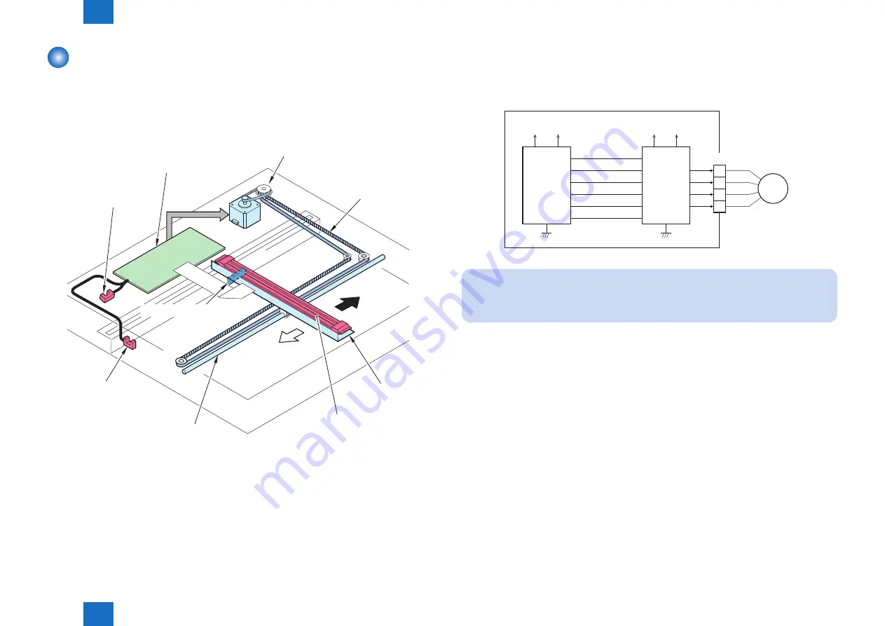
Parts configuration of scanner drive is described below.
Carriage drive belt
Forward
Reverse
Carriage
Carriage rail
Reader motor (M10)
Reader controller PCB (PCB3)
CIS HP sensor (PS24)
Sensor light-blocking plate
Contact image sensor (CIS)
ADF open/closed
detection sensor (PS23)
• Reader motor (M10) drive signal
Controls the rotation and its direction and speed of motor.
• CIS HP sensor (PS24)
Detects that the contact image sensor (CIS) is at the home position.
• ADF open/closed detection sensor (PS23)
Detects the open or close status of the ADF.
F-2-18
●
Reader Motor Control
Reader motor driver (IC15) turns on/off the reader motor (M10) and controls its direction and
speed of rotation according to the signals from ASIC (IC1).
Reader controller PCB
3.3V
+24V
OM_RTPA
OM_RTPAN
OM_RTPB
OM_RTPBN
OM_PS
+5V
J905
B*
B
A
A*
IC1
ASIC
IC15
Motor
driver
1
2
3
4
M10
OM_CURRENT
1.8V
Note:
The scan speed is 160 mm/sec.
F-2-19
Summary of Contents for 1750
Page 12: ...Update Firmware XXV Volume Control XXV Backup Data XXVI...
Page 17: ...1 1 Product Overview Product Overview Product Lineup Features Specifications Parts Name...
Page 235: ...7 7 Error Code Error Code Overview Error Code Jam Code Alarm Code...
Page 250: ...8 8 Service Mode Service Mode Outline Details of Service Mode...
Page 333: ...Service Tools General Timing Chart General Circuit Diagram List of User Mode Appendix...


