background image

Oct 25 2004

Service Manual

Finisher, Sorter, DeliveryTray
3 Way Unit-A1

Summary of Contents for A-1

Page 1: ...Oct 25 2004 Service Manual Finisher Sorter DeliveryTray 3 Way Unit A1 ...

Page 2: ......

Page 3: ... need arises In the event of major changes in the contents of this manual over a long or short period Canon will issue a new edition of this manual The following paragraph does not apply to any countries where such provisions are inconsistent with local law Trademarks The product names and company names used in this manual are the registered trademarks of the individual companies Copyright This ma...

Page 4: ...quiring care to avoid combustion fire Indicates an item prohibiting disassembly to avoid electric shocks or problems Indicates an item requiring disconnection of the power plug from the electric outlet Indicates an item intended to provide notes assisting the understanding of the topic in question Indicates an item of reference assisting the understanding of the topic in question Provides a descri...

Page 5: ...sed to indicate Low The voltage value however differs from circuit to circuit In addition the asterisk as in DRMD indicates that the DRMD signal goes on when 0 In practically all cases the internal mechanisms of a microprocessor cannot be checked in the field Therefore the operations of the microprocessors used in the machines are not discussed they are explained in terms of from sensors to the in...

Page 6: ......

Page 7: ...ary Jam 2 8 2 3 4 Stationary Jam and Cover Open Jam at Power On 2 8 Chapter 3 Parts Replacement Procedure 3 1 Removing from the Host Machine 3 1 3 1 1 3 Way Unit 3 1 3 2 Drive System 3 4 3 2 1 Delivery Motor 2 3 4 3 2 2 Delivery Motor 3 3 6 3 3 Document Feeding System 3 10 3 3 1 Delivery Roller 2 3 10 3 3 2 Reversing Roller 3 13 3 3 3 Delivery Roller 3 3 16 3 3 4 Duplexing Inlet Roller 3 20 3 3 5 ...

Page 8: ...pter 4 Maintenance 4 1 Maintenance and Inspection 4 1 4 1 1 Periodically Replaced Parts 4 1 4 1 2 Durables 4 1 4 1 3 Periodical Servicing 4 1 4 2 Outline of Electrical Components 4 2 4 2 1 Electrical Components 4 2 ...

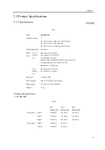
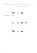
Page 9: ...Chapter 1 Specifications ...

Page 10: ......

Page 11: ...Contents Contents 1 1 Product Specifications 1 1 1 1 1 Specifications 1 1 1 2 Names of Parts 1 3 1 2 1 External View 1 3 1 2 2 Cross Section 1 4 ...

Page 12: ......

Page 13: ...128 g m2 recycled paper eco paper postcard A6R non default postcard 4 pane postcard envelope Monarch DL ISO B5 ISO C5 transparency tracing paper No 3 delivery slot plain paper 64 to 80 g m2 recycled paper eco paper Paper size A3 LDR to B5R Power supply none 24 VDC from host machine Dimensions 176 x 546 x 151 mm WxDxH Weight 3 9 kg No 1 delivery slot No 2 delivery slot No 3 delivery slot Plain pape...

Page 14: ...s 20 sheets No 1 delivery slot No 2 delivery slot No 3 delivery slot plain paper 64g m2 100 sheets 50 sheets 75 sheets 75g m2 100 sheets 50 sheets 75 sheets 80g m2 100 sheets 50 sheets 75 sheets Heavy paper 90g m2 60 sheets 20 sheets 128g m2 60 sheets 20 sheets Special paper label sheet transparency envelope Tracing paper 25 sheets 10 sheets Postcard No 1 delivery slot No 2 delivery slot No 3 deli...

Page 15: ...2 delivery motor 2 No 3 delivery motor 3 Extension delivery kit controller PCB 4 No 3 delivery tray optional Copy Tray J1 5 Reversal slot 6 Reversing guide 7 No 2 delivery tray optional Inner 2 Way Tray D1 1 2 3 7 4 5 6 No 1 delivery slot No 2 delivery slot No 3 delivery slot ...

Page 16: ... No 3 delivery tray optional Copy Tray J1 9 Duplex inlet roller 10 Duplex inlet sensor 11 No 2 delivery flapper 12 No 2 delivery inlet roller 13 No 1 delivery flapper 14 No 2 delivery sensor 15 No 2 delivery roller 16 No 2 delivery tray full sensor 17 No 2 delivery tray optional Inner 2 Way Tray D1 1 2 3 4 5 6 7 8 9 10 11 12 13 14 15 16 17 No 1 delivery slot No 2 delivery slot No 3 delivery slot ...

Page 17: ...Chapter 2 Functions ...

Page 18: ......

Page 19: ... the No 1 Delivery Slot 2 3 2 2 2 Delivery to the No 2 Delivery Slot 2 4 2 2 3 Delivery to the No 3 Delivery Slot 2 5 2 2 4 Movement of Paper in Duplex Mode 2 6 2 3 Detecting Jams 2 7 2 3 1 Arrangement of Sensors 2 7 2 3 2 Delay Jam 2 7 2 3 3 Stationary Jam 2 8 2 3 4 Stationary Jam and Cover Open Jam at Power On 2 8 ...

Page 20: ......

Page 21: ... the extension delivery kit F 2 1 1 No 2 delivery motor 2 No 3 delivery motor 3 Duplex inlet sensor 4 No 3 delivery sensor 5 Extension delivery kit controller PCB 6 No 3 delivery solenoid 7 Duplex delivery solenoid 8 No 1 delivery solenoid 9 No 2 delivery sensor 10 No 2 delivery tray full sensor 1 2 3 4 7 8 9 10 6 5 ...

Page 22: ...livery motor PS1A No 2 delivery sensor PS2A No 2 delivery tray full sensor PS3A Duplex inlet sensor PS4A Reversal sensor PS5A No 3 delivery sensor SL1 No 1 delivery solenoid SL2 No 2 delivery solenoid SL3 No 3 delivery solenoid SL1 SL2 M1 M2 SL3 Reversal guide No 2 delivery slot No 1 delivery slot PS3A PS5A PS4A PS2A PS1A No 3 delivery slot ...

Page 23: ...eration used to discharge paper to the No 1 delivery slot 1 Paper arrives from the delivery slot of the host machine A specific period of time after the leading edge of the paper reaches the fixing outlet sensor PS13 the No 1 delivery solenoid SL1 goes on to help move the paper to the No 1 delivery tray F 2 3 F 2 4 SL1 PS13 ...

Page 24: ...s from the delivery slot of the host machine A specific period of time after the leading edge of the paper reaches the fixing outlet sensor PS13 the No 2 delivery motor M1 starts to rotate The paper then moves forward past the No 2 delivery sensor PS1A and the No 2 delivery tray full sensor PS2A to reach the No 2 delivery tray F 2 5 F 2 6 PS1A PS2A M1 No 2 delivery slot PS13 ...

Page 25: ...he No 2 delivery motor M1 and the No 3 delivery motor M2 starts to rotate F 2 7 2 When the paper moves past the reversal sensor PS4A and its trailing edge reaches a specific point in front of the reversing roller the No 3 delivery motor M2 stops once and then starts again to rotate in reverse direction after a specific period of time At the same time the No 3 delivery solenoid SL3 goes on so that ...

Page 26: ... paper reaches the fixing outlet sensor PS13 the No 2 delivery motor M1 and the No 3 delivery motor M2 start to rotate F 2 10 2 When the paper has moved past the reversal sensor PS4A and its trailing edge reaches a specific point in front of the reversing roller the No 3 delivery motor M2 stops once and starts again to rotate in reverse direction after a specific period of time The paper is moved ...

Page 27: ...2 Delay Jam 0007 6141 The machine will identify a delay jam if any of the foregoing sensors does not go on within a specific period of time The following sensors are used to check for jams T 2 2 Notation Name PS14 No 1 delivery sensor host machine PS1A No 2 delivery sensor PS3A Duplex inlet sensor PS4A Reversal sensor PS5A No 3 delivery sensor PS1A PS4A PS5A PS3A PS14 ...

Page 28: ...l paper when the power is turned on or when its cover is opened The presence of paper will cause the machine to assume the presence of a jam The following shows the sensors used to check for stationary jams and cover open jams when the power is turned on T 2 4 Notation Name PS14 No 1 delivery sensor host machine PS1A No 2 delivery sensor PS3A Duplex inlet sensor PS4A Reversal sensor PS5A No 3 deli...

Page 29: ...Chapter 3 Parts Replacement Procedure ...

Page 30: ......

Page 31: ... Removing the Right Door 3 10 3 3 1 4 Removing the Extension Delivery Kit 3 11 3 3 1 5 Removing the No 2 Delivery Roller 3 12 3 3 2 Reversing Roller 3 13 3 3 2 1 Removing the Inside Delivery Tray Reversal Guide and Inside Upper Cover 3 13 3 3 2 2 Removing the Right Cover rear 3 13 3 3 2 3 Removing the Right Door 3 14 3 3 2 4 Removing the Extension Delivery Kit 3 15 3 3 2 5 Removing the Reversing R...

Page 32: ...uplexing Inlet Sensor 3 35 3 4 4 1 Removing the Inside Delivery Tray Reversal Guide and Inside Upper Cover 3 35 3 4 4 2 Removing the Right Cover rear 3 35 3 4 4 3 Removing the Right Door 3 36 3 4 4 4 Removing the Extension Delivery Kit 3 37 3 4 4 5 Removing the Duplex Inlet Sensor 3 37 3 4 5 Delivery Sensor 3 3 38 3 4 5 1 Removing the Inside Delivery Tray Reversal Guide and Inside Upper Cover 3 38...

Page 33: ... 2 3 Remove the screw 3 and detach the inside upper cover 4 F 3 1 3 1 1 2 Removing the Right Cover rear 0007 6316 1 Open the pedestal right door 1 if equipped with a 2 Cassette Pedestal Y2 2 Open the right lower door 2 3 Remove the 5 screws 3 and detach the right cover rear 4 F 3 2 3 1 1 3 Removing the Right Door 0007 9321 1 Open the right door F 3 3 2 Remove the screw 1 and detach the fixing plat...

Page 34: ...s M4x8 RS tightening F 3 6 5 While freeing the hinge assembly 2 detach the right door F 3 7 Attaching the Right Door 1 Match the hinge 1 found at the bottom of the right door against the lug 2 Engage the hinge 2 found on the top of the right door with the hook found on the side plate F 3 8 When tightening the 2 screws used to fix the hinge in place be sure to close the right door first ...

Page 35: ...clamp 3 and remove the 2 re use bands 4 2 Disconnect the connector 1 from the terminal of the host machine F 3 9 3 Open the extension delivery kit 1 4 Remove the 2 screws 3 5 Remove the 2 screws 2 and close the extension delivery kit F 3 10 6 Detach the extension delivery kit 1 from the host machine F 3 11 ...

Page 36: ...ove the screw 3 and detach the inside upper cover 4 F 3 12 3 2 1 2 Removing the Right Cover rear 0007 6170 1 Open the pedestal right door 1 if equipped with a 2 Cassette Pedestal Y2 2 Open the right lower door 2 3 Remove the 5 screws 3 and detach the right cover rear 4 F 3 13 3 2 1 3 Removing the Right Door 0007 9322 1 Open the right door F 3 14 2 Remove the screw 1 and detach the fixing plate 2 F...

Page 37: ...ge 1 found at the bottom of the right door against the lug 2 Engage the hinge 2 found on the top of the right door with the hook found on the side plate F 3 19 When tightening the 2 screws used to fix the hinge in place be sure to close the right door first 3 2 1 4 Removing the Extension Delivery Kit 0007 6156 1 Free the harness 2 front the cable clamp 3 and remove the 2 re use bands 4 2 Disconnec...

Page 38: ...7 6154 1 Remove the screw 1 and detach the cover 2 2 Disconnect the connector 3 and remove the 2 screws 4 then detach the No 2 delivery motor 5 F 3 23 3 2 2 Delivery Motor 3 3 2 2 1 Removing the Inside Delivery Tray Reversal Guide and Inside Upper Cover 0007 6158 1 Remove the inside delivery tray 1 2 Remove the reversing guide 2 3 Remove the screw 3 and detach the inside upper cover 4 F 3 24 ...

Page 39: ...ws 3 and detach the right cover rear 4 F 3 25 3 2 2 3 Removing the Right Door 0007 9323 1 Open the right door F 3 26 2 Remove the screw 1 and detach the fixing plate 2 F 3 27 3 Remove the joint shaft 1 and free the extension delivery unit 2 from the right door F 3 28 4 Disconnect the connector 1 and remove the reuse band 2 then remove the 2 screws M4x8 RS tightening F 3 29 1 2 3 3 3 4 ...

Page 40: ...htening the 2 screws used to fix the hinge in place be sure to close the right door first 3 2 2 4 Removing the Extension Delivery Kit 0007 6159 1 Free the harness 2 front the cable clamp 3 and remove the 2 re use bands 4 2 Disconnect the connector 1 from the terminal of the host machine F 3 32 3 Open the extension delivery kit 1 4 Remove the 2 screws 3 5 Remove the 2 screws 2 and close the extensi...

Page 41: ...Chapter 3 3 9 3 2 2 5 Removing the No 3 Delivery Motor 0007 6160 1 Disconnect the connector 1 and remove the 2 screws 2 then detach the No 3 delivery motor 3 F 3 35 ...

Page 42: ...2 3 Remove the screw 3 and detach the inside upper cover 4 F 3 36 3 3 1 2 Removing the Right Cover rear 0007 6162 1 Open the pedestal right door 1 if equipped with a 2 Cassette Pedestal Y2 2 Open the right lower door 2 3 Remove the 5 screws 3 and detach the right cover rear 4 F 3 37 3 3 1 3 Removing the Right Door 0007 9324 1 Open the right door F 3 38 2 Remove the screw 1 and detach the fixing pl...

Page 43: ...nge 1 found at the bottom of the right door against the lug 2 Engage the hinge 2 found on the top of the right door with the hook found on the side plate F 3 43 When tightening the 2 screws used to fix the hinge in place be sure to close the right door first 3 3 1 4 Removing the Extension Delivery Kit 0007 6163 1 Free the harness 2 front the cable clamp 3 and remove the 2 re use bands 4 2 Disconne...

Page 44: ...from the host machine F 3 46 3 3 1 5 Removing the No 2 Delivery Roller 0007 6164 1 Open the extension delivery kit F 3 47 2 Disconnect the connector 1 and free the harness from the cable guide F 3 48 3 Remove the E ring 1 F 3 49 4 Remove the E ring 1 and pull out the joint pin 2 then detach the No 2 delivery unit 3 F 3 50 ...

Page 45: ...Guide and Inside Upper Cover 0007 6167 1 Remove the inside delivery tray 1 2 Remove the reversing guide 2 3 Remove the screw 3 and detach the inside upper cover 4 F 3 54 3 3 2 2 Removing the Right Cover rear 0007 6173 1 Open the pedestal right door 1 if equipped with a 2 Cassette Pedestal Y2 2 Open the right lower door 2 3 Remove the 5 screws 3 and detach the right cover rear 4 F 3 55 1 2 3 3 3 4 ...

Page 46: ...y unit 2 from the right door F 3 58 4 Disconnect the connector 1 and remove the reuse band 2 then remove the 2 screws M4x8 RS tightening F 3 59 5 While freeing the hinge assembly 2 detach the right door F 3 60 Attaching the Right Door 1 Match the hinge 1 found at the bottom of the right door against the lug 2 Engage the hinge 2 found on the top of the right door with the hook found on the side pla...

Page 47: ... clamp 3 and remove the 2 re use bands 4 2 Disconnect the connector 1 from the terminal of the host machine F 3 62 3 Open the extension delivery kit 1 4 Remove the 2 screws 3 5 Remove the 2 screws 2 and close the extension delivery kit F 3 63 6 Detach the extension delivery kit 1 from the host machine F 3 64 3 3 2 5 Removing the Reversing Roller 0007 6177 1 Remove the E ring 1 and detach the bushi...

Page 48: ...de Upper Cover 0007 6179 1 Remove the inside delivery tray 1 2 Remove the reversing guide 2 3 Remove the screw 3 and detach the inside upper cover 4 F 3 67 3 3 3 2 Removing the Right Cover rear 0007 6200 1 Open the pedestal right door 1 if equipped with a 2 Cassette Pedestal Y2 2 Open the right lower door 2 3 Remove the 5 screws 3 and detach the right cover rear 4 F 3 68 3 3 3 3 Removing the Right...

Page 49: ...nd 2 then remove the 2 screws M4x8 RS tightening F 3 72 5 While freeing the hinge assembly 2 detach the right door F 3 73 Attaching the Right Door 1 Match the hinge 1 found at the bottom of the right door against the lug 2 Engage the hinge 2 found on the top of the right door with the hook found on the side plate F 3 74 When tightening the 2 screws used to fix the hinge in place be sure to close t...

Page 50: ...of the host machine F 3 75 3 Open the extension delivery kit 1 4 Remove the 2 screws 3 5 Remove the 2 screws 2 and close the extension delivery kit F 3 76 6 Detach the extension delivery kit 1 from the host machine F 3 77 3 3 3 5 Removing the No 3 Delivery Roller 0007 6184 1 Open the extension delivery kit F 3 78 2 Disconnect the 4 connectors 1 and free the cable 2 from the cable guide F 3 79 ...

Page 51: ...n place with your hand so that the assembly will not tumble down 4 Remove the 2 E rings 1 and the joint pin 2 to detach the No 2 delivery assembly 3 F 3 81 5 Remove the 2 E rings 1 2 gears 2 belt 3 pin 4 and 5 screws 5 then detach the plate 6 F 3 82 6 Remove the 2 screws 1 and detach the No 3 delivery frame 2 F 3 83 7 Remove the No 3 delivery roller 1 F 3 84 ...

Page 52: ...he screw 3 and detach the inside upper cover 4 F 3 85 3 3 4 2 Removing the Right Cover rear 0007 6186 1 Open the pedestal right door 1 if equipped with a 2 Cassette Pedestal Y2 2 Open the right lower door 2 3 Remove the 5 screws 3 and detach the right cover rear 4 F 3 86 3 3 4 3 Removing the Right Door 0007 9327 1 Open the right door F 3 87 2 Remove the screw 1 and detach the fixing plate 2 F 3 88...

Page 53: ...nge 1 found at the bottom of the right door against the lug 2 Engage the hinge 2 found on the top of the right door with the hook found on the side plate F 3 92 When tightening the 2 screws used to fix the hinge in place be sure to close the right door first 3 3 4 4 Removing the Extension Delivery Kit 0007 6187 1 Free the harness 2 front the cable clamp 3 and remove the 2 re use bands 4 2 Disconne...

Page 54: ...ler 0007 6188 1 Open the extension delivery kit F 3 96 2 Remove the 3 E rings 1 gear 2 and 2 bushings 3 then detach the duplex inlet roller 4 F 3 97 3 3 5 Inlet Roller 3 3 5 1 Removing the Inside Delivery Tray Reversal Guide and Inside Upper Cover 0007 6189 1 Remove the inside delivery tray 1 2 Remove the reversing guide 2 3 Remove the screw 3 and detach the inside upper cover 4 F 3 98 ...

Page 55: ...s 3 and detach the right cover rear 4 F 3 99 3 3 5 3 Removing the Right Door 0007 9328 1 Open the right door F 3 100 2 Remove the screw 1 and detach the fixing plate 2 F 3 101 3 Remove the joint shaft 1 and free the extension delivery unit 2 from the right door F 3 102 4 Disconnect the connector 1 and remove the reuse band 2 then remove the 2 screws M4x8 RS tightening F 3 103 1 2 3 3 3 4 ...

Page 56: ...htening the 2 screws used to fix the hinge in place be sure to close the right door first 3 3 5 4 Removing the Extension Delivery Kit 0007 6191 1 Free the harness 2 front the cable clamp 3 and remove the 2 re use bands 4 2 Disconnect the connector 1 from the terminal of the host machine F 3 106 3 Open the extension delivery kit 1 4 Remove the 2 screws 3 5 Remove the 2 screws 2 and close the extens...

Page 57: ...6195 1 Open the extension delivery kit F 3 109 2 Remove the 2 screws 1 and detach the cover 2 F 3 110 3 Remove the solenoid lever 1 F 3 111 4 Remove the No 1 delivery flapper 1 and the spring 2 F 3 112 5 Remove the 3 screws 1 and detach the cover 2 F 3 113 ...

Page 58: ...Chapter 3 3 26 6 Remove the 2 E rings 1 and the 2 bushings 2 then detach the inlet roller 3 F 3 114 F 3 115 ...

Page 59: ...emove the screw 3 and detach the inside upper cover 4 F 3 116 3 4 1 2 Removing the Right Cover rear 0007 6203 1 Open the pedestal right door 1 if equipped with a 2 Cassette Pedestal Y2 2 Open the right lower door 2 3 Remove the 5 screws 3 and detach the right cover rear 4 F 3 117 3 4 1 3 Removing the Right Door 0007 9329 1 Open the right door F 3 118 2 Remove the screw 1 and detach the fixing plat...

Page 60: ...nge 1 found at the bottom of the right door against the lug 2 Engage the hinge 2 found on the top of the right door with the hook found on the side plate F 3 123 When tightening the 2 screws used to fix the hinge in place be sure to close the right door first 3 4 1 4 Removing the Extension Delivery Kit 0007 6205 1 Free the harness 2 front the cable clamp 3 and remove the 2 re use bands 4 2 Disconn...

Page 61: ...tension delivery kit 1 from the host machine F 3 126 3 4 1 5 Removing the No 2 Delivery Sensor 0007 6208 1 Open the extension delivery kit F 3 127 2 Remove the 2 screws 1 and detach the cover 2 F 3 128 3 Remove the solenoid lever 1 F 3 129 4 Remove the No 1 delivery flapper 1 and the spring 2 F 3 130 ...

Page 62: ... 1 Removing the Inside Delivery Tray Reversal Guide and Inside Upper Cover 0007 6209 1 Remove the inside delivery tray 1 2 Remove the reversing guide 2 3 Remove the screw 3 and detach the inside upper cover 4 F 3 134 3 4 2 2 Removing the Right Cover rear 0007 6210 1 Open the pedestal right door 1 if equipped with a 2 Cassette Pedestal Y2 2 Open the right lower door 2 3 Remove the 5 screws 3 and de...

Page 63: ...it 2 from the right door F 3 138 4 Disconnect the connector 1 and remove the reuse band 2 then remove the 2 screws M4x8 RS tightening F 3 139 5 While freeing the hinge assembly 2 detach the right door F 3 140 Attaching the Right Door 1 Match the hinge 1 found at the bottom of the right door against the lug 2 Engage the hinge 2 found on the top of the right door with the hook found on the side plat...

Page 64: ... re use bands 4 2 Disconnect the connector 1 from the terminal of the host machine F 3 142 3 Open the extension delivery kit 1 4 Remove the 2 screws 3 5 Remove the 2 screws 2 and close the extension delivery kit F 3 143 6 Detach the extension delivery kit 1 from the host machine F 3 144 3 4 2 5 Removing No 2 Delivery Tray Full Sensor 0007 6212 1 Disconnect the connector 1 and detach the No 2 deliv...

Page 65: ...rew 3 and detach the inside upper cover 4 F 3 146 3 4 3 2 Removing the Right Cover rear 0007 6218 1 Open the pedestal right door 1 if equipped with a 2 Cassette Pedestal Y2 2 Open the right lower door 2 3 Remove the 5 screws 3 and detach the right cover rear 4 F 3 147 3 4 3 3 Removing the Right Door 0007 9331 1 Open the right door F 3 148 2 Remove the screw 1 and detach the fixing plate 2 F 3 149 ...

Page 66: ...nge 1 found at the bottom of the right door against the lug 2 Engage the hinge 2 found on the top of the right door with the hook found on the side plate F 3 153 When tightening the 2 screws used to fix the hinge in place be sure to close the right door first 3 4 3 4 Removing the Extension Delivery Kit 0007 6219 1 Free the harness 2 front the cable clamp 3 and remove the 2 re use bands 4 2 Disconn...

Page 67: ... Duplexing Inlet Sensor 3 4 4 1 Removing the Inside Delivery Tray Reversal Guide and Inside Upper Cover 0007 6221 1 Remove the inside delivery tray 1 2 Remove the reversing guide 2 3 Remove the screw 3 and detach the inside upper cover 4 F 3 158 3 4 4 2 Removing the Right Cover rear 0007 6223 1 Open the pedestal right door 1 if equipped with a 2 Cassette Pedestal Y2 2 Open the right lower door 2 3...

Page 68: ...y unit 2 from the right door F 3 162 4 Disconnect the connector 1 and remove the reuse band 2 then remove the 2 screws M4x8 RS tightening F 3 163 5 While freeing the hinge assembly 2 detach the right door F 3 164 Attaching the Right Door 1 Match the hinge 1 found at the bottom of the right door against the lug 2 Engage the hinge 2 found on the top of the right door with the hook found on the side ...

Page 69: ... remove the 2 re use bands 4 2 Disconnect the connector 1 from the terminal of the host machine F 3 166 3 Open the extension delivery kit 1 4 Remove the 2 screws 3 5 Remove the 2 screws 2 and close the extension delivery kit F 3 167 6 Detach the extension delivery kit 1 from the host machine F 3 168 3 4 4 5 Removing the Duplex Inlet Sensor 0007 6226 1 Disconnect the connector 1 and detach the dupl...

Page 70: ...crew 3 and detach the inside upper cover 4 F 3 170 3 4 5 2 Removing the Right Cover rear 0007 6229 1 Open the pedestal right door 1 if equipped with a 2 Cassette Pedestal Y2 2 Open the right lower door 2 3 Remove the 5 screws 3 and detach the right cover rear 4 F 3 171 3 4 5 3 Removing the Right Door 0007 9333 1 Open the right door F 3 172 2 Remove the screw 1 and detach the fixing plate 2 F 3 173...

Page 71: ...nge 1 found at the bottom of the right door against the lug 2 Engage the hinge 2 found on the top of the right door with the hook found on the side plate F 3 177 When tightening the 2 screws used to fix the hinge in place be sure to close the right door first 3 4 5 4 Removing the Extension Delivery Kit 0007 6230 1 Free the harness 2 front the cable clamp 3 and remove the 2 re use bands 4 2 Disconn...

Page 72: ...the No 3 Delivery Sensor 0007 6232 1 Disconnect the connector 1 and detach the No 3 delivery sensor 2 F 3 181 3 4 6 Delivery Solenoid 1 3 4 6 1 Removing the No 1 Delivery Solenoid 0007 6233 1 Open the right door and open the No 2 delivery assembly 1 then remove the 2 screws 2 and detach the cover 3 F 3 182 2 Remove the solenoid lever 1 and remove the 2 screws 2 F 3 183 ...

Page 73: ...osen the screw 2 and detach the cover 3 Remove the 2 screws 4 and detach the cover 5 F 3 185 3 Remove the spring 1 disconnect the connector 2 and remove the 2 screws 3 then detach the No 2 delivery solenoid 4 F 3 186 3 4 8 Delivery Solenoid 3 3 4 8 1 Removing the No 3 Delivery Solenoid 0007 6235 1 Open the right door and remove the joint pin 1 2 Loosen the screw 2 and detach the cover 3 Remove the...

Page 74: ...320 1 Remove the inside delivery tray 1 2 Remove the reversing guide 2 3 Remove the screw 3 and detach the inside upper cover 4 F 3 189 3 4 9 2 Removing the Right Cover rear 0007 6321 1 Open the pedestal right door 1 if equipped with a 2 Cassette Pedestal Y2 2 Open the right lower door 2 3 Remove the 5 screws 3 and detach the right cover rear 4 F 3 190 3 4 9 3 Removing the Right Door 0007 9334 1 O...

Page 75: ...nd 2 then remove the 2 screws M4x8 RS tightening F 3 194 5 While freeing the hinge assembly 2 detach the right door F 3 195 Attaching the Right Door 1 Match the hinge 1 found at the bottom of the right door against the lug 2 Engage the hinge 2 found on the top of the right door with the hook found on the side plate F 3 196 When tightening the 2 screws used to fix the hinge in place be sure to clos...

Page 76: ...t machine F 3 197 3 Open the extension delivery kit 1 4 Remove the 2 screws 3 5 Remove the 2 screws 2 and close the extension delivery kit F 3 198 6 Detach the extension delivery kit 1 from the host machine F 3 199 3 4 9 5 Removing the Extension Delivery Kit Controller PCB 0007 6319 1 Disconnect the 5 connectors 1 and remove the 2 screws 2 then detach the extension delivery kit controller PCB 3 F ...

Page 77: ...Chapter 4 Maintenance ...

Page 78: ......

Page 79: ... 4 1 1 Periodically Replaced Parts 4 1 4 1 1 1 Periodically Replaced Parts 4 1 4 1 2 Durables 4 1 4 1 2 1 Durables 4 1 4 1 3 Periodical Servicing 4 1 4 1 3 1 Scheduled Servicing 4 1 4 2 Outline of Electrical Components 4 2 4 2 1 Electrical Components 4 2 ...

Page 80: ......

Page 81: ...43 The 3 Way Unit A1 does not have parts that require periodical replacement 4 1 2 Durables 4 1 2 1 Durables 0007 6244 The 3 Way Unit A1 does not have parts that are designated as durables 4 1 3 Periodical Servicing 4 1 3 1 Scheduled Servicing 0007 6245 The 3 Way Unit A1 does not have parts that require scheduled servicing ...

Page 82: ...No 2 delivery path FH7 7312 J744 xx09 PS2A No 2 delivery tray full sensor detects the state full of the No 2 delivery tray FH7 7312 J743 PS3A Duplex inlet sensor detects paper at the inlet to the duplex unit FH7 7312 J742 xx0C PS4A Reversal sensor detects paper at the print of reversal FH7 7312 J745 xx0A PS5A No 3 delivery sensor detects paper in the No 3 delivery path FH7 7312 J742 xx0B PS4A PS5A...

Page 83: ...oller duplex inlet roller and No 3 delivery roller FH5 1021 J743 MTR 15 SL1 No 1 delivery solenoid discharges paper to the No 1 delivery slot FL2 1203 J744 SL2 No 2 delivery solenoid discharges paper to the No 2 delivery slot FL2 1206 J742 SL3 No 3 delivery solenoid discharges paper to the No 3 delivery slot FL2 1205 J742 1 extension delivery kit PCB controls the extension delivery kit FG3 3293 M1...

Page 84: ...Chapter 4 4 4 ...

Page 85: ...Oct 25 2004 ...

Page 86: ......

Reviews: