


<N>
Designated Boot device No. with n=0 corresponding to drive A.
<NEW>
New data is to be loaded into each register or memory. Depending
on command, data is designated in hexadecimal and with two or
four digits.
<OLD>
Read data in each register or memory. The data is displayed in
the hexadecimal and with two or four digits, depending on the
command.
<PORT>
Designated port address in hexadecimal with four digits.
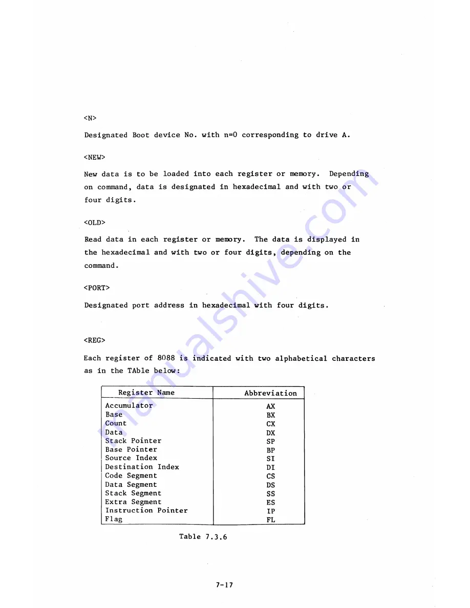
<REG>
Each register of 8088 is indicated with two alphabetical characters
as in the TAble below:
Register Name
Abbreviation
Accumulator
AX
Base
BX
Count
CX
Data
DX
Stack Pointer
SP
Base Pointer
BP
Source Index
SI
Destination Index
DI
Code Segment
CS
Data Segment
DS
Stack Segment
SS
Extra Segment
ES
Instruction Pointer
IP
Flag
FL
Table 7.3.6
7-17
Summary of Contents for AS-100M
Page 1: ...Canon FIELD SERVICE MANUAL ...
Page 26: ...2 2 5 FDD Media Canon specified MDD 512DD 512B sector 2 3 ...
Page 30: ...ICURRENT LÖÖPl Available soon 2 7 ...
Page 39: ...3 3 5 FDD 3 3 1 External View Housing plate Fig 3 3 1 Fig 3 3 2 3 5 ...
Page 41: ...3 4 8 FDD 3 4 1 External View Housing Fig 3 4 1 Fig 3 4 2 3 7 ...
Page 43: ...3 5 PRINTER Refer to PRINTER TECHNICAL GUIDE 3 9 ...
Page 47: ... 2 KEYBOARD 3 5 FDD 4 3 ...
Page 48: ... 8 FDD 4 4 ...
Page 100: ...8 FDD Fuse 1 Replace two 5A fuses 8 FDD as In Fig 5 5 7 5 23 ...
Page 107: ...Chapter 7 Troubleshooting 7 1 At System Up 7 1 ...
Page 129: ...Chapter 8 Appendix 8 1 Unit Configuration and General Wiring ...
Page 130: ...8 1 Unit Configurations and General Wiring 8 1 POWER SWITCH ...
Page 135: ...Fig 8 1 6 8 FDD For 115 120 230 240V POWER SWITCH ...
Page 136: ...CANON INC COPYRIGHT g 198 BY CANON INC Printed in Japan Feb 1983 E Y 8 6 0 7 2 2 2 2 ...


