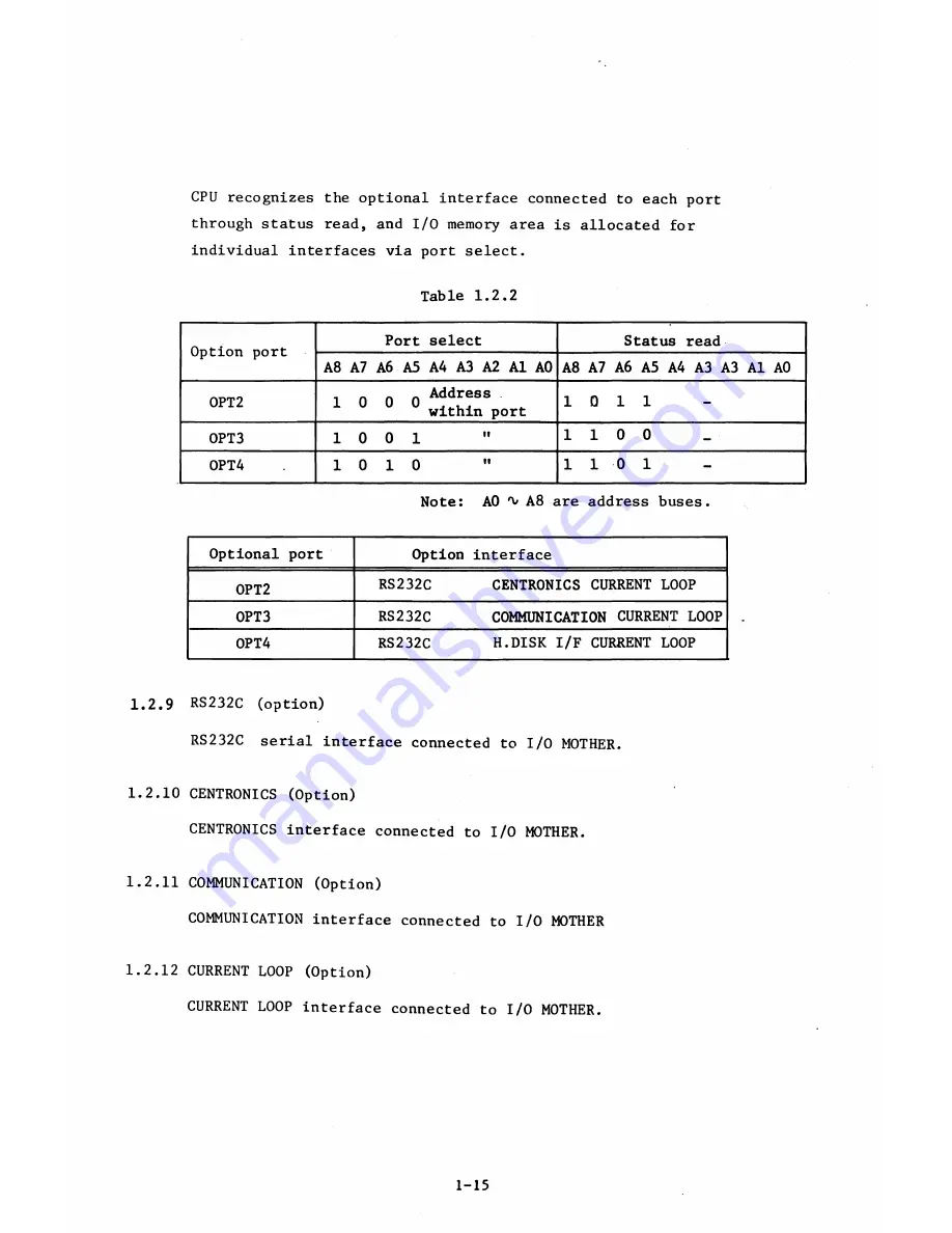
CPU recognizes the optional interface connected to each port
through status read, and I/O memory area is allocated for
individual interfaces via port select.
Table 1.2.2
Option port
Port select
Status read
A
8
A7 A
6
A5 A4 A3 A2 A1 AO A
8
A7 A
6
A5 A4 A3 A3 Al A0
OPT
2
1 0 0
0
Addre8s
•
L u
u within port
1 0
1 1
-
OPT3
1 0
0
1
"
1 1 0
0
_
OPT4
.
1 0
1 0
"
1 1 0
1
-
Note: AO 'v A
8
are address buses.
Optional port
Option interface
0PT2
RS232C
CENTRONICS CURRENT LOOP
0PT3
RS232C
COMMUNICATION CURRENT LOOP
0PT4
RS232C
H.DISK I/F CURRENT LOOP
1.2.9 RS232C (option)
RS232C serial interface connected to I/O MOTHER.
1.2.10 CENTRONICS (Option)
CENTRONICS interface connected to I/O MOTHER.
1.2.11 COMMUNICATION (Option)
COMMUNICATION interface connected to I/O MOTHER
1.2.12 CURRENT LOOP (Option)
CURRENT LOOP interface connected to I/O MOTHER.
1-15
Summary of Contents for AS-100M
Page 1: ...Canon FIELD SERVICE MANUAL ...
Page 26: ...2 2 5 FDD Media Canon specified MDD 512DD 512B sector 2 3 ...
Page 30: ...ICURRENT LÖÖPl Available soon 2 7 ...
Page 39: ...3 3 5 FDD 3 3 1 External View Housing plate Fig 3 3 1 Fig 3 3 2 3 5 ...
Page 41: ...3 4 8 FDD 3 4 1 External View Housing Fig 3 4 1 Fig 3 4 2 3 7 ...
Page 43: ...3 5 PRINTER Refer to PRINTER TECHNICAL GUIDE 3 9 ...
Page 47: ... 2 KEYBOARD 3 5 FDD 4 3 ...
Page 48: ... 8 FDD 4 4 ...
Page 100: ...8 FDD Fuse 1 Replace two 5A fuses 8 FDD as In Fig 5 5 7 5 23 ...
Page 107: ...Chapter 7 Troubleshooting 7 1 At System Up 7 1 ...
Page 129: ...Chapter 8 Appendix 8 1 Unit Configuration and General Wiring ...
Page 130: ...8 1 Unit Configurations and General Wiring 8 1 POWER SWITCH ...
Page 135: ...Fig 8 1 6 8 FDD For 115 120 230 240V POWER SWITCH ...
Page 136: ...CANON INC COPYRIGHT g 198 BY CANON INC Printed in Japan Feb 1983 E Y 8 6 0 7 2 2 2 2 ...


