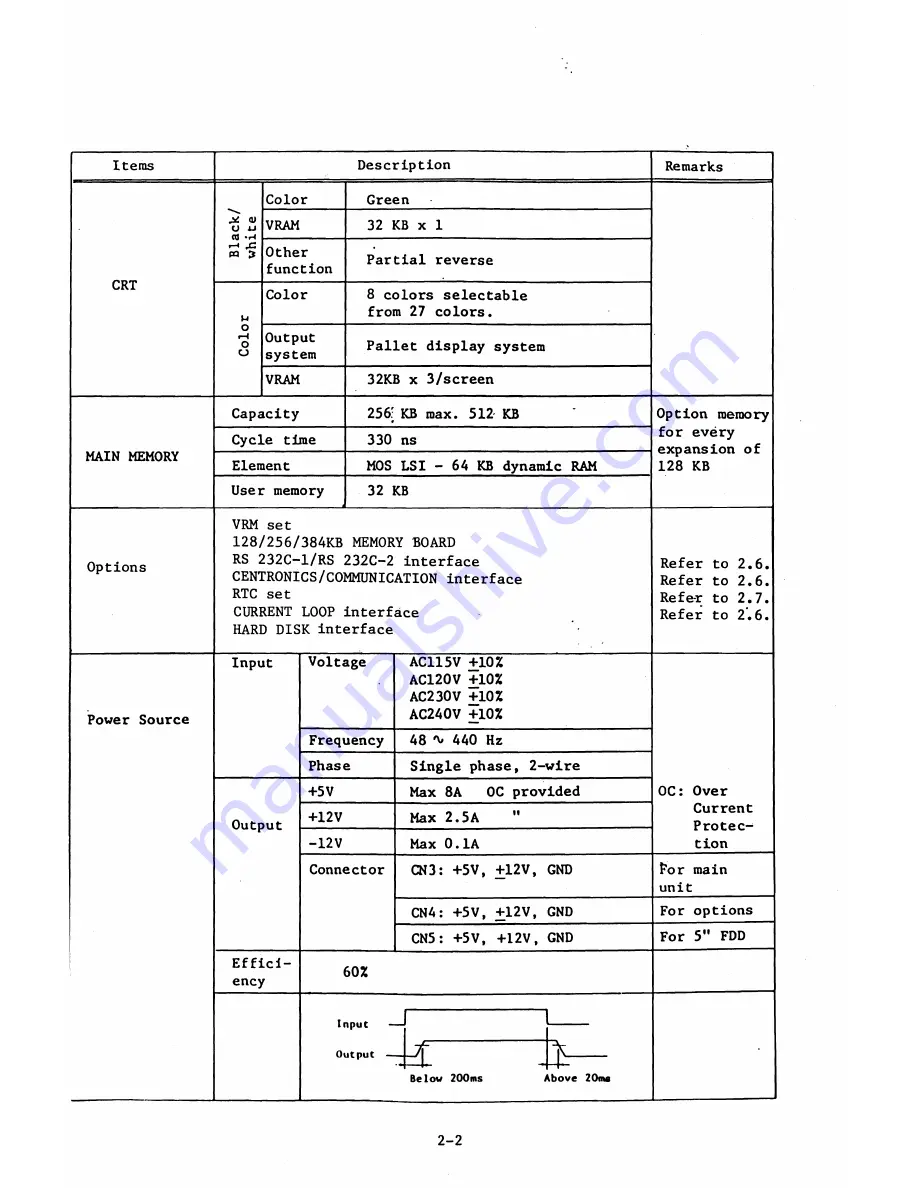
Items
Description
Remarks
Color
Green
B
l
a
c
k
/
wh
ite
VRAM
32 KB x 1
CRT
Other
function
Partial reverse
Color
8
colors selectable
from 27 colors.
O
H
O
CJ
Output
system
Pallet display system
VRAM
32KB x 3/screen
Capacity
256: KB max. 512 KB
'
Option memory
MAIN MEMORY
Cycle time
330 ns
for every
expansion of
128 KB
Element
MOS LSI - 64 KB dynamic RAM
User memory
32 KB
Options
VRM set
128/256/384KB MEMORY BOARD
RS 232C-1/RS 232C-2 interface
Refer to 2.6.
CENTRONICS/COMMUNICATION interface
Refer to 2.6.
RTC set
Refe-r to 2.7.
CURRENT LOOP interface
HARD DISK interface
Refer to 2.6.
Power Source
Input
Output
Effici
ency
Voltage
Frequency
Phase
+5V
+12V
-12V
Connector
10%
10%
10%
10%
48 * 440 Hz
Single phase, 2-wire
Max
8
A
OC provided
Max 2.5A
Max 0.1A
CN3: +5V, +12V, GND
CN4: +5V, +12V, GND
CN5: +5V, +12V, GND
60%
X
Belov 200ms
OC: Over
Current
Protec
tion
For main
unit
For options
For 5" FDD
A bove 20ms
2-2
Summary of Contents for AS-100M
Page 1: ...Canon FIELD SERVICE MANUAL ...
Page 26: ...2 2 5 FDD Media Canon specified MDD 512DD 512B sector 2 3 ...
Page 30: ...ICURRENT LÖÖPl Available soon 2 7 ...
Page 39: ...3 3 5 FDD 3 3 1 External View Housing plate Fig 3 3 1 Fig 3 3 2 3 5 ...
Page 41: ...3 4 8 FDD 3 4 1 External View Housing Fig 3 4 1 Fig 3 4 2 3 7 ...
Page 43: ...3 5 PRINTER Refer to PRINTER TECHNICAL GUIDE 3 9 ...
Page 47: ... 2 KEYBOARD 3 5 FDD 4 3 ...
Page 48: ... 8 FDD 4 4 ...
Page 100: ...8 FDD Fuse 1 Replace two 5A fuses 8 FDD as In Fig 5 5 7 5 23 ...
Page 107: ...Chapter 7 Troubleshooting 7 1 At System Up 7 1 ...
Page 129: ...Chapter 8 Appendix 8 1 Unit Configuration and General Wiring ...
Page 130: ...8 1 Unit Configurations and General Wiring 8 1 POWER SWITCH ...
Page 135: ...Fig 8 1 6 8 FDD For 115 120 230 240V POWER SWITCH ...
Page 136: ...CANON INC COPYRIGHT g 198 BY CANON INC Printed in Japan Feb 1983 E Y 8 6 0 7 2 2 2 2 ...


