


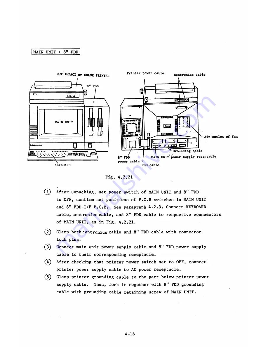
MAIN UNIT + 8" FDD
d o t
IMPACT or COLOR PRINTER
KEYBOARD
Printer power cable
Centronics cable
Fig. 4,2,21
(l) After unpacking, set power switch of MAIN UNIT and 8" FDD
to OFF, confirm set positions of P.C.B switches in MAIN UNIT
and 8n FDD-I/F P.C.B. See parapraph 4*2.3. Connect KEYBOARD
cable, centronics cable, and 8" FDD cable to respective conneectors
of MAIN UNIT, as in Fig. 4.2.21.
(?) Clamp both centronics cable and 8" FDD cable with connector
lock pinsc
(3) Connect main unit power supply cable and 8" FDD power supply
cable to their corresponding receptacle.
(
4
^) After checking that printer power switch set to OFF, connect
printer power supply cable to AC power receptacle.
(
5
) Clamp printer grounding cable to the part below printer power
supply cable. Then, lock it together with 8" FDD grounding
cable with grounding cable retaining screw of MAIN UNIT.
4-16
Summary of Contents for AS-100M
Page 1: ...Canon FIELD SERVICE MANUAL ...
Page 26: ...2 2 5 FDD Media Canon specified MDD 512DD 512B sector 2 3 ...
Page 30: ...ICURRENT LÖÖPl Available soon 2 7 ...
Page 39: ...3 3 5 FDD 3 3 1 External View Housing plate Fig 3 3 1 Fig 3 3 2 3 5 ...
Page 41: ...3 4 8 FDD 3 4 1 External View Housing Fig 3 4 1 Fig 3 4 2 3 7 ...
Page 43: ...3 5 PRINTER Refer to PRINTER TECHNICAL GUIDE 3 9 ...
Page 47: ... 2 KEYBOARD 3 5 FDD 4 3 ...
Page 48: ... 8 FDD 4 4 ...
Page 100: ...8 FDD Fuse 1 Replace two 5A fuses 8 FDD as In Fig 5 5 7 5 23 ...
Page 107: ...Chapter 7 Troubleshooting 7 1 At System Up 7 1 ...
Page 129: ...Chapter 8 Appendix 8 1 Unit Configuration and General Wiring ...
Page 130: ...8 1 Unit Configurations and General Wiring 8 1 POWER SWITCH ...
Page 135: ...Fig 8 1 6 8 FDD For 115 120 230 240V POWER SWITCH ...
Page 136: ...CANON INC COPYRIGHT g 198 BY CANON INC Printed in Japan Feb 1983 E Y 8 6 0 7 2 2 2 2 ...


