


4.3 Installation of Options
4.3.1 I/O-MOTHER-E P.C.B
(T) Remove both rear cover and upper cover. See paragraph
3.1.
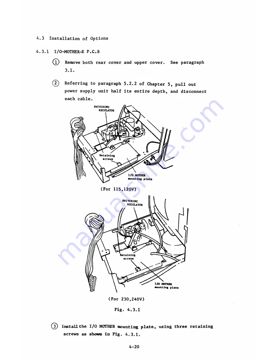
(2) Referring to paragraph 5.2.2 of Chapter 5, pull out
power supply unit half its entire depth, and disconnect
each cable.
(For 115,120V)
Fig. 4.3.1
(T) Install the I/O MOTHER mounting plate, using three retaining
screws as shown in Fig. 4.3.1.
4-20
Summary of Contents for AS-100M
Page 1: ...Canon FIELD SERVICE MANUAL ...
Page 26: ...2 2 5 FDD Media Canon specified MDD 512DD 512B sector 2 3 ...
Page 30: ...ICURRENT LÖÖPl Available soon 2 7 ...
Page 39: ...3 3 5 FDD 3 3 1 External View Housing plate Fig 3 3 1 Fig 3 3 2 3 5 ...
Page 41: ...3 4 8 FDD 3 4 1 External View Housing Fig 3 4 1 Fig 3 4 2 3 7 ...
Page 43: ...3 5 PRINTER Refer to PRINTER TECHNICAL GUIDE 3 9 ...
Page 47: ... 2 KEYBOARD 3 5 FDD 4 3 ...
Page 48: ... 8 FDD 4 4 ...
Page 100: ...8 FDD Fuse 1 Replace two 5A fuses 8 FDD as In Fig 5 5 7 5 23 ...
Page 107: ...Chapter 7 Troubleshooting 7 1 At System Up 7 1 ...
Page 129: ...Chapter 8 Appendix 8 1 Unit Configuration and General Wiring ...
Page 130: ...8 1 Unit Configurations and General Wiring 8 1 POWER SWITCH ...
Page 135: ...Fig 8 1 6 8 FDD For 115 120 230 240V POWER SWITCH ...
Page 136: ...CANON INC COPYRIGHT g 198 BY CANON INC Printed in Japan Feb 1983 E Y 8 6 0 7 2 2 2 2 ...


