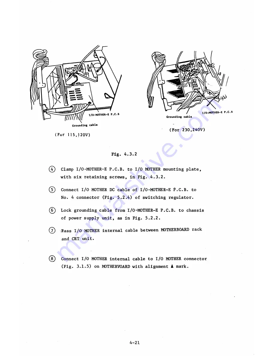
Grounding cable
(For 115,120V)
(For 230,240V)
Fig. 4.3.2
(4) Clamp I/O-MOTHER-E P.C.B. to I/O MOTHER mounting plate,
with six retaining screws, in Fig. 4.3.2.
©
Connect I/O MOTHER DC cable of I/0-M0THER-E f.C.B. to
No. 4 connector (Fig. 5.2.4) of switching regulator.
(6) Lock grounding cable from I/O-MOTHER-E P.C.B. to chassis
of power supply unit, as in Fig. 5.2.2.
©
Rass I/O MOTHER internal cable between MOTHERBOARD rack
and CRT unit.
( © Connect I/O MOTHER internal cable to I/O MOTHER connector
(Fig. 3.1.5) on M0THERV0ARD with alignment
A
mark.
4-21
Summary of Contents for AS-100M
Page 1: ...Canon FIELD SERVICE MANUAL ...
Page 26: ...2 2 5 FDD Media Canon specified MDD 512DD 512B sector 2 3 ...
Page 30: ...ICURRENT LÖÖPl Available soon 2 7 ...
Page 39: ...3 3 5 FDD 3 3 1 External View Housing plate Fig 3 3 1 Fig 3 3 2 3 5 ...
Page 41: ...3 4 8 FDD 3 4 1 External View Housing Fig 3 4 1 Fig 3 4 2 3 7 ...
Page 43: ...3 5 PRINTER Refer to PRINTER TECHNICAL GUIDE 3 9 ...
Page 47: ... 2 KEYBOARD 3 5 FDD 4 3 ...
Page 48: ... 8 FDD 4 4 ...
Page 100: ...8 FDD Fuse 1 Replace two 5A fuses 8 FDD as In Fig 5 5 7 5 23 ...
Page 107: ...Chapter 7 Troubleshooting 7 1 At System Up 7 1 ...
Page 129: ...Chapter 8 Appendix 8 1 Unit Configuration and General Wiring ...
Page 130: ...8 1 Unit Configurations and General Wiring 8 1 POWER SWITCH ...
Page 135: ...Fig 8 1 6 8 FDD For 115 120 230 240V POWER SWITCH ...
Page 136: ...CANON INC COPYRIGHT g 198 BY CANON INC Printed in Japan Feb 1983 E Y 8 6 0 7 2 2 2 2 ...


