


5.3 KEYBOARD
5.3.1 KEYBOARD (outer cover)
(J)
Remove outer cover according to paragraph 5.3.2.
(2)
Care should be taken not to accidentally cut pointing device
cable inside keyboard in removal.
5.3.2 KEY TOP
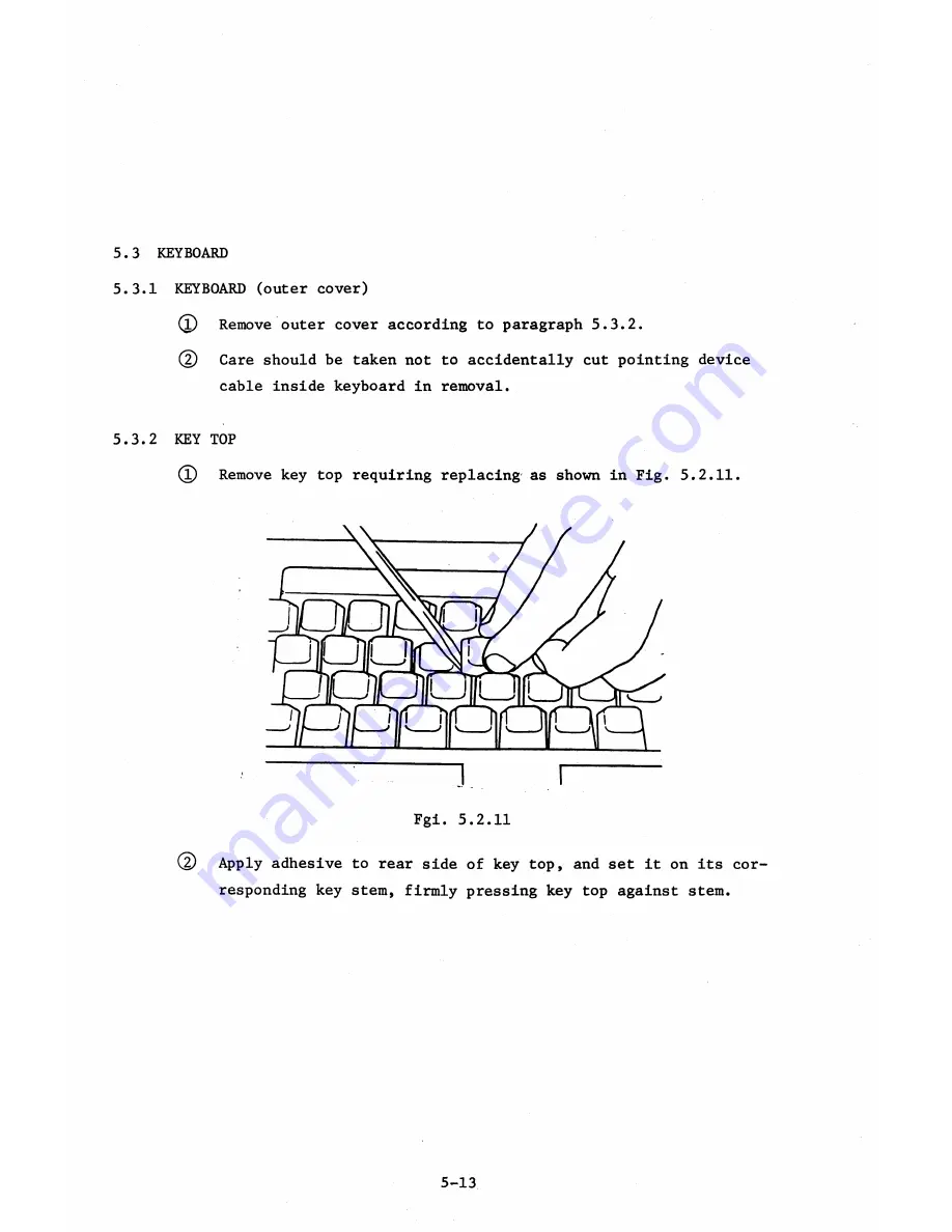
(l)
Remove key top requiring replacing as shown in Fig. 5.2.11.
Fgi. 5.2.11
(D
Apply adhesive to rear side of key top, and set it on its cor
responding key stem, firmly pressing key top against stem.
5-13
Summary of Contents for AS-100M
Page 1: ...Canon FIELD SERVICE MANUAL ...
Page 26: ...2 2 5 FDD Media Canon specified MDD 512DD 512B sector 2 3 ...
Page 30: ...ICURRENT LÖÖPl Available soon 2 7 ...
Page 39: ...3 3 5 FDD 3 3 1 External View Housing plate Fig 3 3 1 Fig 3 3 2 3 5 ...
Page 41: ...3 4 8 FDD 3 4 1 External View Housing Fig 3 4 1 Fig 3 4 2 3 7 ...
Page 43: ...3 5 PRINTER Refer to PRINTER TECHNICAL GUIDE 3 9 ...
Page 47: ... 2 KEYBOARD 3 5 FDD 4 3 ...
Page 48: ... 8 FDD 4 4 ...
Page 100: ...8 FDD Fuse 1 Replace two 5A fuses 8 FDD as In Fig 5 5 7 5 23 ...
Page 107: ...Chapter 7 Troubleshooting 7 1 At System Up 7 1 ...
Page 129: ...Chapter 8 Appendix 8 1 Unit Configuration and General Wiring ...
Page 130: ...8 1 Unit Configurations and General Wiring 8 1 POWER SWITCH ...
Page 135: ...Fig 8 1 6 8 FDD For 115 120 230 240V POWER SWITCH ...
Page 136: ...CANON INC COPYRIGHT g 198 BY CANON INC Printed in Japan Feb 1983 E Y 8 6 0 7 2 2 2 2 ...


