background image

Digital X-ray Imager

Technical Document

AX-B2735W

2.4 GHz/5 GHz

000_DIA-2019-002-E04_AX-B2735W.book  Page 1  Friday, November 27, 2020  12:22 PM

Summary of Contents for AX-B2735W

Page 1: ...Digital X ray Imager Technical Document AX B2735W 2 4 GHz 5 GHz 000_DIA 2019 002 E04_AX B2735W book Page 1 Friday November 27 2020 12 22 PM ...

Page 2: ...ge under abnormal conditions 2 Roentgenography image processing image reading and image data storage must be performed in accordance with the laws of the country or region in which the product is being used The user is responsible for maintaining the privacy of image data 3 In no event shall Canon be liable for personal physical harm or property damage that is sustained when the instructions are n...

Page 3: ...ady indicator exchanging a hook and loop fastener 36 4 4 1 Removing the hook and loop fastener from the ready indicator and attachment position 36 4 4 2 Attaching the ready indicator behind the monitor of a control software installed laptop computer 36 4 4 3 Attaching a ready indicator to a wall or post 37 5 Troubleshooting 39 Error codes on the error code display 40 6 Maintenance 41 Maintenance a...

Page 4: ...Electromagnetic Disturbances 52 Electromagnetic emissions 53 Electromagnetic immunity 54 Recommended separation distances 56 Appendix Technical description 57 EMD Electromagnetic Disturbances 58 000_DIA 2019 002 E04_AX B2735W book Page 4 Friday November 27 2020 12 22 PM ...

Page 5: ...This notice is used to identify conditions under which improper use of the product may cause property damage Pay attention to the caution message This is used to indicate a prohibited operation This is used to indicate an action that must be performed This is used to indicate important instructions that must be followed and restrictions Be sure to read the notices to avoid property damage or malfu...

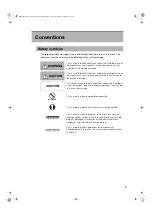
Page 6: ...Conventions 6 000_DIA 2019 002 E04_AX B2735W book Page 6 Friday November 27 2020 12 22 PM ...

Page 7: ...1 Safety information The precautions described in this chapter prevent users and others from suffering damage or loss 000_DIA 2019 002 E04_AX B2735W book Page 7 Friday November 27 2020 12 22 PM ...

Page 8: ...esult in fire or electric shock Handling Never disassemble or modify the device Doing so could result in fire or electric shock Do not place anything on top of the device The object may fall and cause an injury Also if metal objects such as needles or clips fall into the device or if liquid is spilled it could result in fire or electric shock Do not hit or drop the device The device may be damaged...

Page 9: ...n the device is going to be cleaned be sure to turn OFF the power to each piece of equipment remove the battery pack Never use alcohol benzine thinner or any other flammable solvents Otherwise it could result in fire For safety reasons be sure to turn OFF the power to each piece of equipment when the inspections of the device and cables are going to be performed Otherwise electric shocks may occur...

Page 10: ...a temperature range of 5 C to 35 C When using the detector if you observe an abnormal rise in temperature above the temperatures listed below stop using it immediately The maximum temperature of the detector 45 C This is measured during maximum load test when the ambient temperature is set to 35 C Avoid doing the following actions to the detector during exposure ready status Otherwise the detector...

Page 11: ...and lock the battery cover Do not open or close the battery cover when the device gets wet If necessary wrap the device in a disposable cover The battery cover is a consumable item If the battery cover is deformed or the packing is damaged or cracked replace the battery cover with a new one If a deteriorated battery cover continues to be used water leakage may occur Turn OFF the power to each piec...

Page 12: ...y pack Handle the device carefully as it is precision device The inner device may be damaged if something hits against it or if it is dropped or receives a strong jolt Be sure to use the device on a flat surface while using it in horizontal position If the detector is set on a diagonal and pressure is applied to it the inner device may be damaged Be sure to securely hold the device while using it ...

Page 13: ... the battery pack wipe it with a cloth slightly damped with water or diluted neutral detergent The battery pack is not protected against liquids When cleaning the battery pack wipe it carefully so as not to spill the detergents onto the electrodes Dry the battery pack completely after cleaning and attach it to the device When cleaning any other parts than the sensor side of the detector wipe them ...

Page 14: ...e conditions described below When not in use keep the detector in a designated location or in a location where they are safe and cannot fall down CAUTION Prohibited Temperature Humidity Atmospheric pressure Operating environment 5ºC to 35ºC 30 to 80 RH 613 to 1060 hPa Storage environment 5ºC to 40ºC 30 to 85 RH 000_DIA 2019 002 E04_AX B2735W book Page 14 Friday November 27 2020 12 22 PM ...

Page 15: ...erence to radio communications Operation of this equipment in a residential area is likely to cause harmful interference in which case the user will be required to correct the interference at his own expense This transmitter must not be co located or operated in conjunction with any other antenna or transmitter RF exposure compliance The available scientific evidence does not show that any health ...

Page 16: ...ing used Whereas high levels of RF can produce health effects by heating tissue exposure of low level RF that does not produce heating effects causes no known adverse health effects Many studies of low level RF exposures have not found any biological effects Some studies have suggested that some biological effects might occur but such findings have not been confirmed by additional research AX B273...

Page 17: ...non Inc δηλώνει ότι ο παρών εξοπλισμός συμμορφώνεται με την Οδηγία 2014 53 ΕΕ Το πλήρες κείμενο της δήλωσης συμμόρφωσης της ΕΕ διατίθεται στην ακόλουθη διεύθυνση στο διαδίκτυο https global canon en deoco medcom index html French Le soussigné Canon Inc déclare que le présent équipement est conforme à la Directive 2014 53 UE Le texte complet de la déclaration UE de conformité est disponible à l adre...

Page 18: ...r Canon Inc att denna utrustning överensstämmer med direktiv 2014 53 EU Den fullständiga texten till EU försäkran om överensstämmelse finns tillgänglig på följande webbadress https global canon en deoco medcom index html Romanian Prin prezenta Canon Inc declară că acest echipament este în conformitate cu Directiva 2014 53 UE Textul integral al declarației UE de conformitate este disponibil la urmă...

Page 19: ... produto contém a placa RF Module BM72065 código de homologação ANATEL 05807 18 07857 Para consultas visite www anatel gov br Frequency band Wireless LAN standard IEEE 802 Frequency band MHz Modulation Data rate Mbps Effective radiation power dBm 2 4 GHz 11b 2412 2472 DSSS 11 Max 12 48 11g OFDM 54 11n HT20 75 HT40 2422 2462 150 Max 11 99 5 GHz 11a 5180 5320 5500 5700 OFDM 54 Max 17 35 11n HT20 75 ...

Page 20: ...acts Keep the detector safe from strong impacts The detector has the waterproof protection equivalent to IPX7 but there is no guarantee it will stay free of damage if it is dropped or otherwise subjected to a strong impact Disinfection and cleaning Do not use highly invasive or corrosive disinfectants or solvents When disinfecting the sensor side of the detector wipe it with a disinfecting cloth a...

Page 21: ...2 Introduction 000_DIA 2019 002 E04_AX B2735W book Page 21 Friday November 27 2020 12 22 PM ...

Page 22: ...odels but now with water resistance equivalent to IPX7 The LED lamps on the ready indicator light up or flash and the indicator beeps to indicates the beginning and end of exposure ready status of the detector countdown alarms as well as X ray detection At the time of installation set a specific channel in the frequency band of 2 4 GHz 5 GHz before using the LAN X Ray Digital Imager AX B2735W is a...

Page 23: ...3 Parts names and functions 000_DIA 2019 002 E04_AX B2735W book Page 23 Friday November 27 2020 12 22 PM ...

Page 24: ...maining battery pack charge D READY switch E READY LED This LED lamp flashes while the detector is transitioning to exposure ready status and lights up when the detector enters exposure ready status Also flashes approx 3 seconds when detector linkage is initiated Flashes in the case of errors F Error code display If errors occur an error code is displayed G IR data port Communication port for the ...

Page 25: ...enables to attach or remove the battery pack detector s battery for wireless configuration K Cable connector Accepts the wiring cable L Effective imaging area border Indicates the effective imaging area and center position 000_DIA 2019 002 E04_AX B2735W book Page 25 Friday November 27 2020 12 22 PM ...

Page 26: ...r use may not be usable in outdoor areas depending on local radio frequency regulations When configuring other wireless LAN equipment do not use the same radio frequency channel that is selected for this product Otherwise an interference between the two pieces of equipment may occur and may result in a decline in transmission speed and other troubles Before introducing other wireless equipment to ...

Page 27: ...unication with the detector which registers the detector to the laptop computer 3 3 Ready indicator Do not install the ready indicator such a position that its IR data port faces the monitor reflector or other IR data communication equipment except for the detector A Mute switch Slide to to enable the mute function and to to disable the mute function B LED status indicator Lights up or flashes to ...

Page 28: ...3 Parts names and functions 28 000_DIA 2019 002 E04_AX B2735W book Page 28 Friday November 27 2020 12 22 PM ...

Page 29: ...4 Operating procedures 000_DIA 2019 002 E04_AX B2735W book Page 29 Friday November 27 2020 12 22 PM ...

Page 30: ...ery slowly discharges even if not in use The battery pack may have expired if it discharges immediately after being fully charged You can purchase an optional battery pack to replace an exhausted one Information Place the detector on a flat surface before commencing the steps below Otherwise the battery pack may fall out while it is being attached Information Cover lock Battery cover Do not lift t...

Page 31: ...own on the front of the battery cover to lock it Check the orientation of the battery pack before inserting it Attach the battery pack carefully Make sure that the battery pack is correctly attached Make sure that the battery pack is inserted fully Important Important Important Information If foreign objects are found on the rubber wipe them off If there are kinks in the rubber fix them by hand In...

Page 32: ...hape of the battery cover and if the inside of the cover has warped into a curved shape replace it with a new battery cover Make sure that the battery cover is inserted fully Make sure that the battery cover is locked securely The remaining battery pack charge is indicated by the Power LED lamps of the detector when the detector is turned on Power LED Remaining battery charge 76 to 100 51 to 75 26...

Page 33: ...e two LED lamps on the ready indicator flash three times for 0 5 seconds at 0 5 second intervals and a three tone beep is emitted Proceed to the next Connection Communication link is automatically established between the internal wireless module of the detector and the wireless access point control system 3 Conduct examination Registration Connection To reduce exposure to RF energy during examinat...

Page 34: ...ure that READY LED is lit This means that the system is ready to start an examination The LED lamps on the ready indicator light up or flash and the ready indicator beeps to indicate the detector status The READY LED on the detector flashes during preparation for examinations When the detector and control system are in exposure ready status the READY LED on the detector and two LED lamps on the re...

Page 35: ...ingers into the slot of the battery pack bay to grip the battery pack edge and then pull the edge to remove the battery pack iii Attach the battery cover 4 3 Ending use of the detector When the detector will not be used for some time remove the battery pack Otherwise overdischarge may occur leading to a shorter battery life Information 000_DIA 2019 002 E04_AX B2735W book Page 35 Friday November 27...

Page 36: ...ray environment 1 Attach hook and loop fasteners i Apply fastener loops to the ready indicator on the side of the volume buttons on the positioning rib The fastener loops are attached using the adhesive on the back 4 4 Attaching the ready indicator exchanging a hook and loop fastener The fastener hooks and fastener loops can be applied to either the ready indicator or to the location where you wan...

Page 37: ...vironments as an X ray exposure room 1 Attach hook and loop fasteners i Apply the fastener loops to the ready indicator on the side of the speaker holes on the positioning rib The fastener loops are attached using the adhesive on the back ii Apply the fastener hook where you want to attach the ready indicator on a wall or post Fastener hook 4 4 3 Attaching a ready indicator to a wall or post Posit...

Page 38: ...and loop fastener to the attachment position of the ready indicator Check that the volume adjustment buttons and the mute switch can be operated and that the LED lamps and IR data port can be seen 000_DIA 2019 002 E04_AX B2735W book Page 38 Friday November 27 2020 12 22 PM ...

Page 39: ...5 Troubleshooting 000_DIA 2019 002 E04_AX B2735W book Page 39 Friday November 27 2020 12 22 PM ...

Page 40: ...ernal memory Exposure is not possible The internal memory must be replaced Contact your sales representative 48 A problem has occurred with the detector s internal memory Contact your sales representative 99 Insufficient space in the detector s internal memory is preventing exposure Transfer images to the control computer 000_DIA 2019 002 E04_AX B2735W book Page 40 Friday November 27 2020 12 22 PM...

Page 41: ...6 Maintenance 000_DIA 2019 002 E04_AX B2735W book Page 41 Friday November 27 2020 12 22 PM ...

Page 42: ...Ensure that there is no dust dirt or oil on the terminals of the cable connector 6 Ensure that the battery cover is not damaged or bent 7 Ensure that there is nothing wrong with the rubber in the battery cover foreign objects tears cracks etc After turning on the power 1 Perform test exposure Ensure that captured images are displayed normally on the monitor Maintenance and inspection Daily inspect...

Page 43: ...7 Specifications 000_DIA 2019 002 E04_AX B2735W book Page 43 Friday November 27 2020 12 22 PM ...

Page 44: ...ntal requirements Operation Temperature Humidity Atmospheric pressure 5 C to 35 C 30 to 80 RH without condensation 613 to 1060 hPa Storage unpacked Temperature Humidity Atmospheric pressure 5 C to 40 C 30 to 85 RH without condensation 613 to 1060 hPa Transportation in packages at point of purchase Temperature Humidity Atmospheric pressure 30 C to 50 C 10 to 95 RH without condensation 613 to 1060 h...

Page 45: ...8 Regulatory information 000_DIA 2019 002 E04_AX B2735W book Page 45 Friday November 27 2020 12 22 PM ...

Page 46: ...s and markings on the detector Detector Product label Details of markings Direct current This mark indicates that this equipment must be handled with care Certification mark that indicates the product complies with the safety standards For U S A and Canada 000_DIA 2019 002 E04_AX B2735W book Page 46 Friday November 27 2020 12 22 PM ...

Page 47: ...9 Dimensional diagram 000_DIA 2019 002 E04_AX B2735W book Page 47 Friday November 27 2020 12 22 PM ...

Page 48: ...9 Dimensional diagram 48 AX B2735W Detector Unit mm 384 15 7 307 5 Ready indicator Unit mm 35 140 20 000_DIA 2019 002 E04_AX B2735W book Page 48 Friday November 27 2020 12 22 PM ...

Page 49: ...10 Product components 000_DIA 2019 002 E04_AX B2735W book Page 49 Friday November 27 2020 12 22 PM ...

Page 50: ...Pack LB 4A Ready indicator RI 3A Hook and loop fastener fastener hooks fastener loops One pair is already applied to the product 3 pairs Battery Charger BC 1A Battery charger 1 Power cord 1 Basic components Optional parts 000_DIA 2019 002 E04_AX B2735W book Page 50 Friday November 27 2020 12 22 PM ...

Page 51: ...11 Guidance and manufacturer s declaration for EMD 000_DIA 2019 002 E04_AX B2735W book Page 51 Friday November 27 2020 12 22 PM ...

Page 52: ... the other equipment should be observed to verify that they are operating normally 3 To maintain the optimum EMD performance use only the designated cables 4 WARNING Use of accessories transducers and cables other than those specified or provided by the manufacturer of this equipment could result in increased electromagnetic emissions or decreased electromagnetic immunity of this equipment and res...

Page 53: ...tic Environment Guidance RF emissions CISPR11 GROUP 1 The AX B2735W uses RF energy only for its internal function Therefore its RF emissions are very low and are not likely to cause any interference in nearby electromagnetic equipment RF emissions CISPR11 Class A The AX B2735W is suitable for use in all establishments other than domestic and those directly connected to the public low voltage power...

Page 54: ...kV common mode 1 kV differential mode 2 kV common mode Mains power quality should be that of a typical commercial environment Voltage dips short interruptions and voltage variations on power supply input lines IEC 61000 4 11 0 UT 0 5 cycle 0 45 90 135 180 225 270 and 315 0 UT 1 cycle and 70 UT 25 30 cycles Single phase at 0 0 UT 250 300 cycles 0 UT 0 5 cycle 0 45 90 135 180 225 270 and 315 0 UT 1 ...

Page 55: ... Radiated RF IEC 61000 4 3 3 V 150 kHz to 80 MHz 3 V m 80 MHz to 2 7 GHz 3 V 3 V m Portable and mobile RF communications equipment should be used no closer to any part of the AX B2735W including cables than the recommended separation distance calculated from the equation applicable to the frequency of the transmitter Recommended separations distance d 1 2 d 1 2 80 MHz to 800 MHz d 2 3 800 MHz to 2...

Page 56: ...itter m 150 kHz to 80 MHz d 1 2 80 MHz to 800 MHz d 1 2 800 MHz to 2 7 GHz d 2 3 0 01 0 12 0 12 0 23 0 1 0 38 0 38 0 73 1 1 2 1 2 2 3 10 3 8 3 8 7 3 100 12 12 23 For transmitters rated at a maximum output power not listed above the recommended separation distance d in meters m can be estimated using the equation applicable to the frequency of the transmitter where P is the maximum output power rat...

Page 57: ...Appendix Technical description 000_DIA 2019 002 E04_AX B2735W book Page 57 Friday November 27 2020 12 22 PM ...

Page 58: ... an outlet on a circuit different from that to which the other devices are connected If the problem cannot be solved with the above measures stop using this equipment and consult your sales representative For details about this product s emission class group and immunity test level see 11 Guidance and manufacturer s declaration for EMD page 51 EMD Electromagnetic Disturbances 000_DIA 2019 002 E04_...

Page 59: ...000_DIA 2019 002 E04_AX B2735W book Page 59 Friday November 27 2020 12 22 PM ...

Page 60: ...awasaki Kanagawa 211 8501 Japan Telephone 81 3 3758 2111 Distributed by CANON MEDICAL COMPONENTS U S A INC 15955 ALTON PARKWAY IRVINE CA 92618 U S A Telephone 1 800 970 7227 Revision Date 2020 12 000_DIA 2019 002 E04_AX B2735W book Page 60 Friday November 27 2020 12 22 PM ...

Reviews: