2.5.5 When the ASF gear initial position adjustment is required
When installing the ASF, the ASF gear initial position adjustment must be executed to
match phase with the purge unit's ASF drive gear, which is the transmission source of
the ASF drive, and the ASF gear.
Preparing for the Adjustment:
Make sure that the purge unit's ASF drive gear is in the initial position when
assembling. If it is in the initial position, assemble the printer with the ASF unit
removed, and Procedures 1) through 3) are not necessary. If it is not in the initial
position, follow the adjustment procedures described below.
1) Manually rotate the ASF drive gear slowly in the direction of the arrow to move it to
the initial position.
2) Stop rotating the gear until a click can be felt (where the rotation stops).
(To confirm the position, gently move the ASF drive gear vertically with your
fingers. Make sure that the gear is at the position where click can be felt.)
3) If the gear has passed the click position, rotate the gear in the arrow's direction to
return to the correct position.
Adjustment Procedures
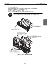
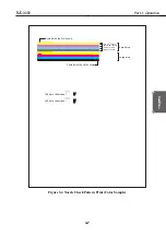
1) Rotate the pick-up roller to place the ASF unit's cam and the mark in the position
shown in
Figure 2-17
.
2) Hold the gear still with your fingers and fix the ASF unit to the printer chassis by
screw. Align the projection of the ASF gear with the indention of the ASF drive gear.
Placing the hooks on the upper side of the ASF and slowly swinging the ASF down
will ease the installation.
3) Fix the ASF unit to the printer chassis with screws to keep the adjusted gear
position.
2-15
BJC-3000
Part 2: Maintenance
Maintenance
ASF Drive Gear
Cam
Mark
Mark
Mark
Mark
Projection
Indention
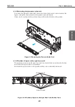
Figure 2-16 ASF Drive Gear Initial Position
Figure 2-17 ASF Gear Initial Position Adjustment
Summary of Contents for BJC-3000 Series
Page 2: ...0899 SC 0 30 0 ...
Page 3: ......
Page 12: ...VIII This page intentionally left blank ...
Page 14: ......
Page 28: ......
Page 48: ...Part 2 Maintenance BJC 3000 2 20 This page intentionally left blank ...
Page 50: ......
Page 62: ...Part 3 Operation BJC 3000 3 12 This page intentionally left blank ...
Page 64: ......
Page 88: ......
Page 95: ......
Page 112: ...Part 5 Appendix BJC 3000 5 24 This page intentionally left blank ...
Page 118: ......
Page 119: ...PRINTED IN JAPAN IMPRIME AU JAPON CANON INC The printing paper contains 70 waste paper ...


