5
5
5-53
5-53
Adjustment > Adjustment at Time of Parts Replacement > Adjustment After Replacing Finisher Controller PCB
Adjustment > Adjustment at Time of Parts Replacement > Adjustment After Replacing Finisher Controller PCB
20)
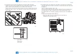
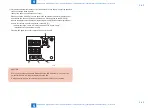
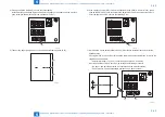
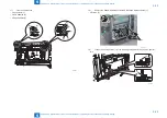
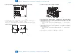
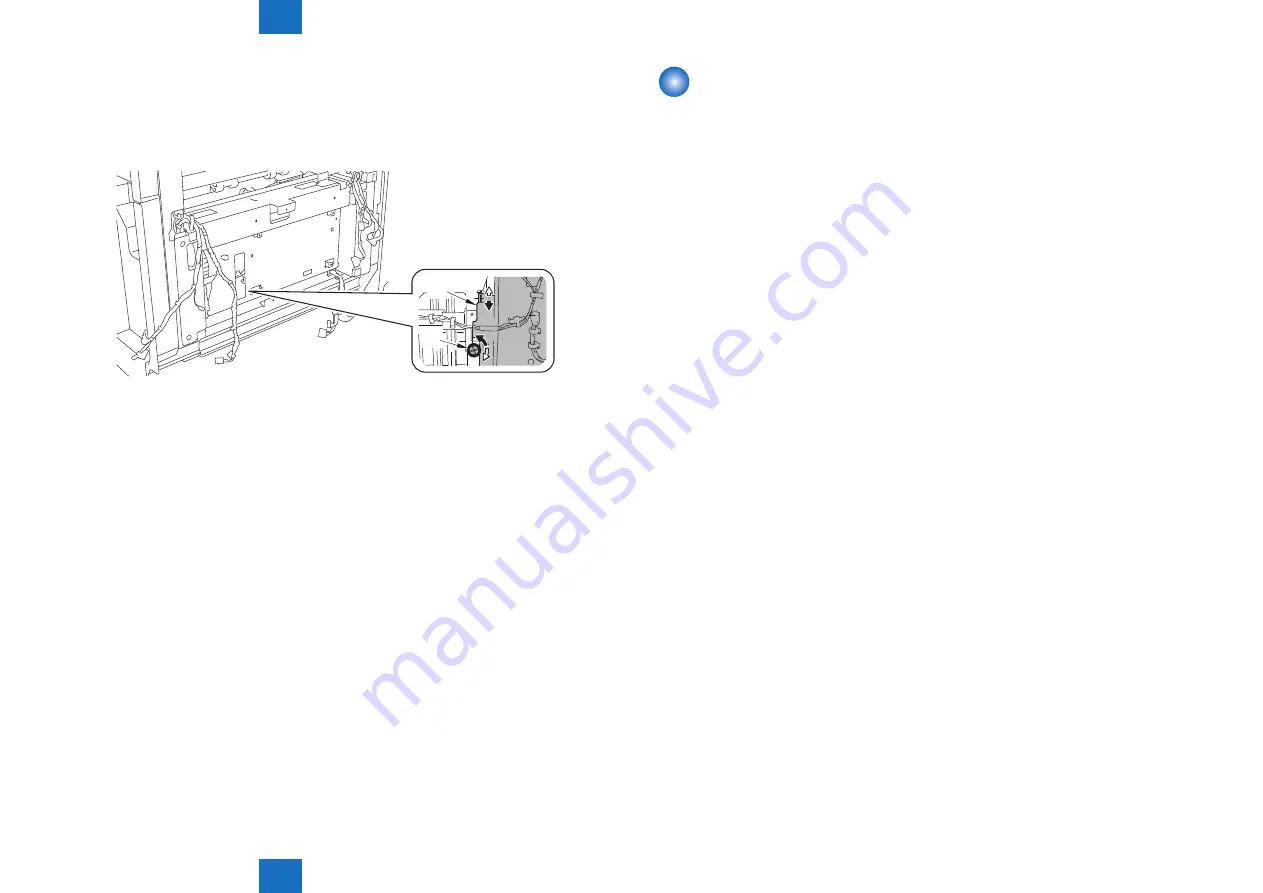
Correct the position of the stopper fixture according to the displacement amount (C)
for folding position that was measured in step 1).
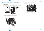
Procedure: Turn the cross-hole screw [1] to adjust the position of the lead edge stopper
fixture [2] upward/downward.
(0.5mm-change per turn)
[1]
[2]
21)
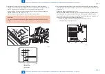
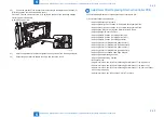
After the adjustment is completed, tighten the fixing screw of the lead edge stopper.
22)
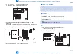
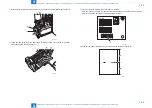
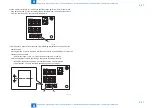
Output the paper from the saddle assembly and check the result.
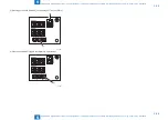
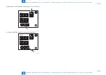
F-5-124
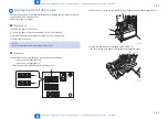
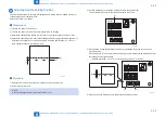
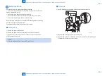
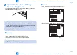
Adjustment After Replacing Finisher Controller PCB
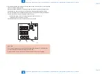
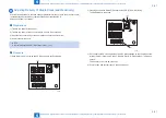
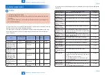
Execute this adjustment when replacing the finisher controller PCB.
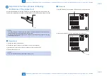
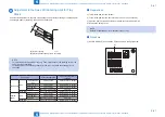
1) Execute the following adjustments:
• Adjusting Sensor Light Intensity
• Adjusting the Alignment Position of the Upper Neat Alignment Plate
• Adjusting the Alignment Position of the Lower Neat Alignment Plate
• Adjusting the Height of Corrugation Roller for Stack Delivery
• Adjusting Alignment Plate Position
• Adjusting Staple Position (1-stapling at the rear)
• Adjusting Staple Position (1-stapling at the front)
• Adjusting Staple Position (2-stapling positions)
• Adjusting Delivery of Staple Stack (lower delivery)
• Adjusting Delivery of Staple Stack (saddle delivery)
• Adjusting Delivery of Staple Stack (lower delivery)
• Adjusting Delivery of Staple Stack (saddle delivery)
• Adjusting Position of Saddle Lead Edge Stopper
• Adjusting Saddle Stitching Position
• Adjusting Saddle Folding Position
• Bufferless Mode
• Adjustment in the Case of Failure in Stacking Performance of Tray (upper curl)
• Adjustment in the Case of Failure in Stacking Performance of Tray (lower curl)
• Adjustment in the Case of Failure in Stacking Performance of Tray (run-on of paper
Summary of Contents for Booklet Finisher-D1
Page 12: ... Notes Before Servicing Points to Note at Cleaning Safety Precautions ...
Page 14: ...1 1 Product Outline Product Outline Product Specifications Names of Parts ...
Page 60: ...3 3 Periodic Servicing Periodic Servicing User Maintenance Maintenance and Inspection ...
Page 315: ...6 6 Troubleshooting Troubleshooting Upgrading ...
Page 357: ... Service Tools Solvents and Oils List of Signals General Circuit Diagram Appendix ...

