background image

Aug 23 2004

Service Manual

Drum Unit
C-EXV 11/12

Summary of Contents for C-EXV 11

Page 1: ...Aug 23 2004 Service Manual Drum Unit C EXV 11 12 ...

Page 2: ......

Page 3: ... need arises In the event of major changes in the contents of this manual over a long or short period Canon will issue a new edition of this manual The following paragraph does not apply to any countries where such provisions are inconsistent with local law Trademarks The product names and company names used in this manual are the registered trademarks of the individual companies Copyright This ma...

Page 4: ...quiring care to avoid combustion fire Indicates an item prohibiting disassembly to avoid electric shocks or problems Indicates an item requiring disconnection of the power plug from the electric outlet Indicates an item intended to provide notes assisting the understanding of the topic in question Indicates an item of reference assisting the understanding of the topic in question Provides a descri...

Page 5: ...sed to indicate Low The voltage value however differs from circuit to circuit In addition the asterisk as in DRMD indicates that the DRMD signal goes on when 0 In practically all cases the internal mechanisms of a microprocessor cannot be checked in the field Therefore the operations of the microprocessors used in the machines are not discussed they are explained in terms of from sensors to the in...

Page 6: ......

Page 7: ...s Chapter 1 Installation 1 1 Installation Procedure 1 1 1 1 1Turning Off the Host Machine 1 1 1 1 2Replacing the Drum Unit 1 1 1 1 3After Replacing the Drum Unit APVC correction 1 4 1 1 4Attaching the Counter Label 1 4 ...

Page 8: ......

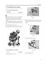
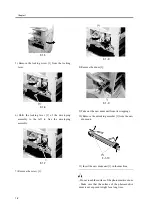
Page 9: ...Chapter 1 Installation ...

Page 10: ......

Page 11: ...s Contents 1 1 Installation Procedure 1 1 1 1 1 Turning Off the Host Machine 1 1 1 1 2 Replacing the Drum Unit 1 1 1 1 3 After Replacing the Drum Unit APVC correction 1 4 1 1 4 Attaching the Counter Label 1 4 ...

Page 12: ......

Page 13: ...ough the shutdown sequence indicated on the screen so that the machine will be ready to be turned off 3 Turn off the main power switch 4 Disconnect the power cable from the wall outlet F 1 1 1 1 2 Replacing the Drum Unit 0007 3185 1 Open the upper front cover 1 F 1 2 2 Remove the face rubber piece 1 and the 2 screws 2 then slide the front cover unit 3 to the left to detach F 1 3 3 Remove the waste...

Page 14: ...assembly F 1 7 7 Remove the screw 1 F 1 8 8 Remove the drum 1 F 1 9 9 Take out the new drum unit from its wrappings 10 Remove the unlocking member 1 from the new drum unit F 1 10 11 Insert the new drum unit 1 in the machine Do not touch the surface of the photosensitive drum Make sure that the surface of the photosensitive drum is not exposed to light for a long time ...

Page 15: ...loping assembly to the right to lock it in place F 1 13 14 Secure the locking lever in place using a screw 1 F 1 14 15 Close the right door 16 Fit the waste toner box F 1 15 17 Using 2 screws 2 mount the front cover unit 3 then fit the face rubber member 1 At this time be sure to slide the front cover to the right so that its claws will match the host machine ...

Page 16: ...er inside the cassette If no paper exists in cassette 1 the machine will try to find paper in the lower cassettes in order The paper will be discharged blank to end APVC correction 4 Press the Reset key twice to end service mode 1 1 4 Attaching the Counter Label 0007 3345 1 Press the Counter key on the control panel to check the total counter reading 2 Press the Close key on the LCD to go back to ...

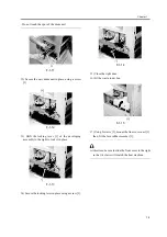
Page 17: ...Chapter 1 1 5 F 1 20 6 Close the upper front cover 1 F 1 21 ...

Page 18: ......

Page 19: ...Aug 23 2004 ...

Page 20: ......

Reviews: