background image

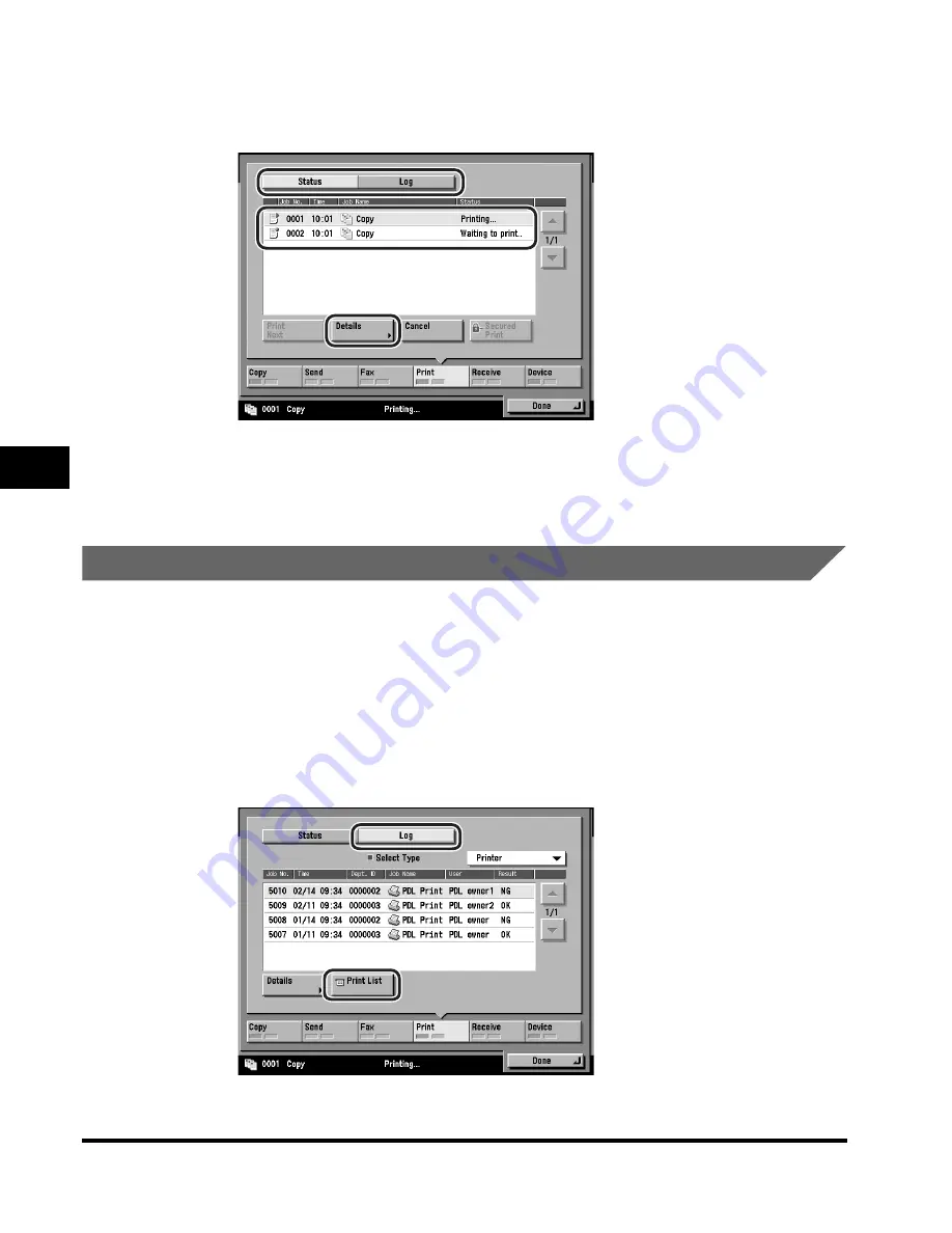
Job Details

5-12

5

Chec

king Job and De

vice Status

2

Press [Status] or [Log] 

 select the job whose details you 

want to check 

 press [Details].

3

Check the detailed information 

 press [Done] repeatedly 

until the Basic Features screen appears.


Printing the Copy/Print Log

1

Press [System Monitor] 

 select the job type ([Copy] or 

[Print]).

If necessary, see the screen shot in step 1 of "Checking Copy/Print Job Details," 
on p. 5-11.

2

Press [Log] 

 [Print List].

Summary of Contents for C3220

Page 1: ...Read this guide first Please read this guide before operating this equipment After you finish reading this guide store it in a safe place for future reference ENG Reference Guide Reference Guide ...

Page 2: ......

Page 3: ...Color imageRUNNER C3220 C2620 Reference Guide 0 Ot ...

Page 4: ...ructions Mail Box Guide Sending and Fax Instructions Sending and Facsimile Guide Setting Up the Network Connection and Installing the CD ROM Software Network Quick Start Guide Remote User Interface Instructions Remote UI Guide CD ROM Network Connectivity and Setup Instructions Network Guide CD ROM Color Network ScanGear Installation and Instructions Color Network ScanGear User s Guide CD ROM PS PC...

Page 5: ...dministrator Guide CD ROM To view the manual in PDF format Adobe Reader Acrobat Reader Acrobat is required If Adobe Reader Acrobat Reader Acrobat is not installed on your system please download it from the Adobe Systems Incorporated website http www adobe com The machine illustration on the cover may differ slightly from your machine ...

Page 6: ... Chapter 8 Troubleshooting Chapter 9 Appendix Includes the specifications of the main unit and optional equipment the Relationship between Original Orientation and Preprinted Paper Output Chart and index How This Manual Is Organized Considerable effort has been made to ensure that this manual is free of inaccuracies and omissions However as we are constantly improving our products if you need an e...

Page 7: ...s Used in This Manual xx Trademarks xx Copyright xxi Disclaimers xxi Legal Limitations on the Usage of Your Product and the Use of Images xxii Important Safety Instructions xxiv Installation xxiv Power Supply xxvi Handling xxvii Maintenance and Inspections xxx Consumables xxxi Other Warnings xxxii Periodic Inspection of the Breaker xxxiii Checking the Breaker xxxiii Check Sheet for the Periodic In...

Page 8: ... 2 8 Various Touch Panel Display Screens 2 10 Adding New Functions 2 11 Specifying Settings 2 13 Functions That Conserve Power 2 14 Checking Changing and Canceling Print Jobs 2 16 Displaying a Help Screen 2 18 Reading Messages from the System Manager 2 20 Types of Message Boards 2 20 Other Useful Functions 2 22 Using the Touch Panel Display 2 25 Frequently Used Keys 2 25 Touch Panel Key Display 2 ...

Page 9: ...Functions 3 18 Finishing Modes 3 19 Finisher N1 Saddle Finisher N2 3 22 Parts and Their Functions 3 22 Finishing Modes 3 23 Copy Tray Unit H1 3 28 Parts and Their Functions 3 28 Card Reader D1 3 29 Procedure before Using the Machine 3 30 Procedure after Using the Machine 3 31 Department ID Management 3 32 Changing the Password and Page Limit 3 32 Checking the Page Counts on a Control Card 3 42 Che...

Page 10: ...iting Irregular Paper Sizes 4 58 Naming a Size Key 4 61 Erasing Irregular Paper Sizes 4 62 Standard Local Print Settings 4 65 Changing the Language Shown on the Touch Panel Display 4 68 Reversing the Contrast of the Touch Panel Display 4 70 Alternating the Print Output Offset Jobs 4 72 Data Compression Ratio for Remote Scans 4 74 Setting the Gamma Value for Remote Scans 4 76 Erasing the Remaining ...

Page 11: ...he Department ID Password and Page Limit 6 8 Changing the Password and Page Limit 6 16 Erasing the Department ID and Password 6 20 Checking and Printing Counter Information 6 24 Clearing Page Totals 6 28 Accepting Print and Scan Jobs with Unknown IDs 6 32 Accepting B W Copy and Print Jobs without Entering a Department ID 6 35 Remote UI 6 38 Device Information Settings 6 40 Clearing the Message Boa...

Page 12: ... and Cover 7 39 Manual Feeder Cleaning 7 40 Cleaning the Inside of the Main Unit 7 43 Automatic Feeder Cleaning 7 45 Consumables 7 47 Chapter 8 Troubleshooting Reducing the Frequency of Paper Jams 8 2 Clearing Paper Jams 8 3 Screens Indicating the Locations of Paper Jams 8 3 Upper Left Cover 8 9 Exit Slot Cover 8 12 Fixing Unit Inside the Main Unit 8 17 Duplexing Unit Inside the Main Unit 8 21 Sta...

Page 13: ...our Local Authorized Canon Dealer 8 85 When the Power Does Not Turn ON 8 88 Chapter 9 Appendix Sample Reports 9 2 Copy Log List 9 2 Print Log List 9 3 Specifications 9 5 Main Unit 9 5 Color Image Reader C1 9 7 Feeder DADF K1 9 9 Cassette Feeding Unit X1 9 9 Plain Pedestal C1 9 10 Paper Deck P1 9 10 Finisher M1 9 11 Finisher N1 9 12 Saddle Finisher N2 9 13 Copy Tray Unit H1 9 15 Card Reader D1 9 15...

Page 14: ...erning operations that may lead to death or injury to persons if not performed correctly In order to use the machine safely always pay attention to these warnings CAUTION Indicates a caution concerning operations that may lead to injury to persons or damage to property if not performed correctly In order to use the machine safely always pay attention to these cautions IMPORTANT Indicates operation...

Page 15: ...oard Resolution Switching Board Color Network Multi PDL Printer Kit Saddle Finisher N2 and Cassette Feeding Unit X1 Note that functions that cannot be used depending on the model or options are not displayed on the touch panel display The keys which you should press are marked with a as shown below When multiple keys can be pressed on the touch panel display all keys are marked Select the keys whi...

Page 16: ...Used in This Manual Illustrations used in this manual are those displayed when the Color imageRUNNER C3220 Copier model has the following optional equipment attached to it the Feeder DADF K1 and Cassette Feeding Unit X1 ...

Page 17: ...so various kinds of prints may sometimes have to wait their turn before they can be printed out To avoid confusion when reading this manual the terms scanning printing and copying used throughout this manual are defined below When making a copy the process of scanning originals and printing copies may be described as separate functions Operations and Terms Used in This Manual Scanning Scanning an ...

Page 18: ...xvi Printing data scanned from an original followed by finishing options such as stapling Copying ...

Page 19: ...d in a commercial environment This equipment generates uses and can radiate radio frequency energy and if not installed and used in accordance with the Operator s Manual may cause harmful interference to radio communications Operation of this equipment in a residential area is likely to cause harmful interference in which case the user will be required to correct the interference at his own expens...

Page 20: ... Health and Human Services DHHS Radiation Performance Standard according to the Radiation Control for Health and Safety Act of 1968 Also this product is certified as a Class I laser product under IEC60825 1 1993 and EN60825 1 1994 This means that the product does not produce hazardous laser radiation Since radiation emitted inside the product is completely confined within protective housings and e...

Page 21: ... products marketed in the United States The label shown below is attached to the laser scanner unit inside the machine or to the cover of the laser scanner unit CAUTION Use of controls adjustments or performance of procedures other than those specified in this manual may result in hazardous radiation exposure CANON INC 3 30 2 SHIMOMARUKO OHTA KU TOKYO JAPAN CANON U S A INC ONE CANON PLAZA LAKE SUC...

Page 22: ...United States and other countries NetWare is a registered trademark of Novell Inc Java and all Java based trademarks and logos are trademarks or registered trademarks of Sun Microsystems Inc in the U S or other countries Ethernet is a trademark of Xerox Corporation The following fonts are licensed from Bitstream Technologies Inc Dutch 801 Bold Dutch 801 Roman Fixed Pitch 810 Courier 10 Pitch Text ...

Page 23: ...ge without notice CANON INC MAKES NO WARRANTY OF ANY KIND WITH REGARD TO THIS MATERIAL EITHER EXPRESS OR IMPLIED EXCEPT AS PROVIDED HEREIN INCLUDING WITHOUT LIMITATION THEREOF WARRANTIES AS TO MARKETABILITY MERCHANTABILITY FITNESS FOR A PARTICULAR PURPOSE OF USE OR AGAINST INFRINGEMENT OF ANY PATENT CANON INC SHALL NOT BE LIABLE FOR ANY DIRECT INCIDENTAL OR CONSEQUENTIAL DAMAGES OF ANY NATURE OR L...

Page 24: ... print or otherwise reproduce any particular document and or of the use of the images scanned printed or otherwise reproduced you should consult in advance with your legal advisor for guidance Paper Money Travelers Checks Money Orders Food Stamps Certificates of Deposit Passports Postage Stamps canceled or uncanceled Immigration Papers Identifying Badges or Insignias Internal Revenue Stamps cancel...

Page 25: ...s can be prevented by using the optional Key Switch Unit to manage the operation of the Color imageRUNNER C3220 C2620 The use of this key should be strictly supervised Security Key When using the machine insert the security key into the main unit and then turn it to the right ...

Page 26: ...nty Installation WARNING Do not install the machine near alcohol paint thinner or other flammable substances If flammable substances come into contact with electrical parts inside the machine it may result in a fire or electrical shock Do not place the following items on the machine If these items come into contact with a high voltage area inside the machine it may result in a fire or electrical s...

Page 27: ...ion of working parts inside the machine Blocking these openings can cause the machine to overheat Never place the machine on a soft surface such as a sofa or rug Do not install the machine in the following locations A damp or dusty location A location near water faucets or water A location exposed to direct sunlight A location subject to high temperatures A location near open flames Do not remove ...

Page 28: ... other than the power cord provided as this may result in a fire or electrical shock As a general rule do not use extension cords Using an extension cord may result in a fire or electrical shock If an extension cord must be used however use one rated for voltages of 120 V AC and over untie the cord binding and insert the power plug completely into the extension cord outlet to ensure a firm connect...

Page 29: ...onents inside the machine it may result in a fire or electrical shock To avoid damage to the power cord and creating a fire hazard always turn OFF the main power switch and unplug the interface cable when moving the machine Otherwise the power cord or interface cable may be damaged resulting in a fire or electrical shock Do not drop paper clips staples or other metal objects inside the machine Als...

Page 30: ...e used for a long period of time such as overnight Also turn OFF the main power switch and disconnect the power cord for safety when the machine will not be used for an extended period of time such as during consecutive holidays Do not place your hand in the part of the tray where stapling is performed when a finisher is attached as this may result in personal injury The laser beam can be harmful ...

Page 31: ...xxix Do not remove the caution label attached to the cover of the laser scanner unit If the laser beam escapes from the machine exposure may cause serious damage to your eyes ...

Page 32: ...result in a fire Clean the machine using a slightly dampened cloth with a mild detergent mixed with water Do not use alcohol benzene paint thinner or other flammable substances Check detergent for flammability prior to use If flammable substances come into contact with a high voltage area inside the machine it may result in a fire or electrical shock There are some areas inside the machine which a...

Page 33: ...immediately consult a physician When loading paper or removing jammed originals or paper take care not to cut your hands on the edges of the originals or paper When removing a used toner cartridge remove the cartridge carefully to prevent the toner from scattering and getting into your eyes or mouth If the toner gets into your eyes or mouth wash them immediately with cold water and immediately con...

Page 34: ...her Warnings WARNING For cardiac pacemaker users This product generates a low level magnetic field If you use a cardiac pacemaker and feel abnormalities please move away from the product and consult your doctor ...

Page 35: ...s turned ON and the machine is neither printing nor scanning before inspecting the breaker If a malfunction occurs after an inspection contact your local authorized Canon dealer Checking the Breaker 1 Push the test button with the tip of a ball point pen or a similar object IMPORTANT Briefly push the test button NOTE The breaker is located on the back of the machine Periodic Inspection of the Brea...

Page 36: ... OFF If the breaker lever does not switch to the OFF side position repeat step 1 If the breaker lever does not switch to the OFF side position despite carrying out the above procedure two or three times contact your local authorized Canon dealer 3 Once you have confirmed that the power is OFF press the main power switch to OFF side ON I side OFF side ON I side OFF side ...

Page 37: ...the breaker lever to ON I side 5 Press the main power switch to ON I side 6 Fill in the check sheet located on the next page to document your periodic inspections of the breaker ON I side OFF side ON I side OFF side ...

Page 38: ...Breaker on p xxxiii once or twice a month How to Fill in This Check Sheet Fill in the date of inspection and the name of the inspector When the inspection is completed successfully write a check mark under OK If not contact your local authorized Canon dealer Also write a check mark under NG No Good Check Sheet for the Periodic Inspection of the Breaker Date of Inspection Date of Inspection Inspect...

Page 39: ... how to turn ON the main power Installation Location and Handling 1 2 Installation Precautions 1 2 Handling Precautions 1 8 Parts and Their Functions 1 12 External View 1 12 Internal View 1 14 Control Panel Parts and Functions 1 16 Main Power and Control Panel Power 1 17 How to Turn ON the Main Power 1 17 Control Panel Power Switch 1 27 System Settings 1 28 ...

Page 40: ...ion and handling We recommend that you read this section prior to using this machine Installation Precautions Avoid Installing the Machine in the Following Locations Avoid locations subject to temperature and humidity extremes whether low or high For example avoid installing the machine near water faucets hot water heaters humidifiers air conditioners heaters or stoves ...

Page 41: ...erfere with the electrical cord or power supply Avoid poorly ventilated locations This machine generates a slight amount of ozone during normal use Although sensitivity to ozone may vary this amount is not harmful Ozone may be more noticeable during extended use or long production runs especially in poorly ventilated rooms It is recommended that the room be appropriately ventilated sufficient to m...

Page 42: ...where a considerable amount of dust accumulates Avoid locations where ammonia gas is emitted Avoid locations near volatile or flammable materials such as alcohol or paint thinner Avoid locations that are subject to vibration For example avoid installing the machine on unstable floors or stands ...

Page 43: ... vibrations generated by the machine during printing can adversely affect the operation of such equipment Avoid installing the machine near televisions radios or similar electronic equipment The machine might interfere with sound and picture signal reception Insert the power plug into a dedicated power outlet and maintain as much space as possible between the machine and other electronic equipment...

Page 44: ...steady voltage Do not connect other electrical equipment to the same power outlet to which the machine is connected Do not connect the power cord to a multiplug power strip as this may cause a fire or electrical shock The power cord may become damaged if it is often stepped on or if heavy objects are placed on it Continued use of a damaged power cord can lead to an accident such as a fire or elect...

Page 45: ...Provide enough space on each side of the machine for unrestricted operation The Optional Platen Cover Type G is attached The optional Color Image Reader C1 Feeder DADF K1 Finisher M1 and Paper Deck P1 are attached 71 1 4 1 809 mm 47 1 192 mm 3 15 16 100 mm or more 85 5 8 2 174 mm 47 1 192 mm 3 15 16 100 mm or more ...

Page 46: ...art Using This Machine Moving the Machine If you intend to move the machine even to a location on the same floor of your building contact your local authorized Canon dealer beforehand Handling Precautions Do not attempt to disassemble or modify the machine ...

Page 47: ... such as paper clips or staples inside the machine If a foreign object comes into contact with electrical parts inside the machine it might cause a short circuit and result in a fire or electrical shock If there is smoke or unusual noise immediately turn the main power switch OFF disconnect the power cord from the outlet and call your local authorized Canon dealer Using the machine in this state m...

Page 48: ... amount is not harmful Ozone may be more noticeable during extended use or long production runs especially in poorly ventilated rooms It is recommended that the room be appropriately ventilated sufficient to maintain a comfortable working environment in areas of machine operation For safety reasons turn OFF the control panel power switch of the machine when it will not be used for a long period of...

Page 49: ...product s hard disk drive be duplicated or backed up to prevent its loss in the event of failure or other malfunction of the hard disk drive Neither Canon nor any service provider will be liable for damages for loss of data stored on the product s hard disk drive See the terms of the product s Limited Warranty for more details ...

Page 50: ...ow you the copier model For more information on optional equipment parts and their functions see Chapter 3 Optional Equipment NOTE The Color Image Reader C1 is standard equipment on the Color imageRUNNER C3220 C2620 Copier model External View a a a a Center Output Tray Prints are output to this tray b b b b Control Panel Includes the keys touch panel display and indicators required for operating t...

Page 51: ...on to periodically test the circuit breaker See Periodic Inspection of the Breaker on p xxxiii i i i i Breaker Detects excess current or leakage current See Periodic Inspection of the Breaker on p xxxiii j j j j Platen Cover Type G Optional The Platen Cover Type G secures originals placed on the platen glass k k k k Color Image Reader C1 Optional for the Base Printer Model Scans and reads images t...

Page 52: ...Reader C1 and Feeder DADF K1 are attached c c c c Stack Bypass Use the stack bypass to feed paper manually and for loading irregular paper stock such as envelopes See Making Prints Using the Stack Bypass on p 2 43 d d d d Security Key Optional For managing the use of the machine and preventing unauthorized copies See Legal Limitations on the Usage ofYour Product and the Use of Images on p xxii e e...

Page 53: ... Open this cover to replace the toner cartridges and waste toner container See Replacing the Toner Cartridge on p 7 28 or Replacing the Waste Toner Container on p 7 34 i i i i Waste Toner Container Collects the waste toner j j j j Toner Cartridge When toner runs out pull out the toner cartridge and replace it with a new one Replace all toner cartridges through their respective ports Toner cartridg...

Page 54: ...tructions that appear on the touch panel display When the Error indicator maintains a steady red light contact your local authorized Canon dealer k k k k Processing Data Indicator Flashes or blinks green when the machine is performing operations and maintains a steady green light when fax data is stored in memory l l l l Numeric keys Press to enter numerical values m m m m Additional Functions key...

Page 55: ...at detects excess current or leakage current How to Turn ON the Main Power This section explains how to turn ON the main power 1 Make sure that the power plug is firmly inserted into the power outlet WARNING Do not connect or disconnect the power cord with wet hands as this may result in electrical shock 2 If the optional security key is inserted into the machine make sure that it is in the ON pos...

Page 56: ...r OFF first turn the control panel power switch OFF and then press the main power switch to the side The main power indicator on the control panel lights when the main power switch is turned ON IMPORTANT If the main power indicator on the control panel does not light even though the main power switch is ON be sure to check the breaker to see if it is OFF See When the Power Does Not Turn ON on p 8 ...

Page 57: ... set and an application other than MEAP is selected as the initial function in Common Settings from the Additional Functions screen The Start Up screen is displayed until the machine is ready to scan If a message is displayed on the touch panel display proceed to step 5 The machine is ready to scan in approximately 45 seconds at a room temperature of 68 after the screen above appears The screen be...

Page 58: ...n the case above the standard settings are selected The standard copy settings are The standard settings for each function of the machine Copy Mail Box Send and Fax are already set at the factory but you can change them to suit your needs See Chapter 9 Customizing Settings in the Copying Guide Chapter 6 Customizing Settings in the Mail Box Guide and Chapter 9 Customizing Communications Settings in...

Page 59: ...ommon Settings from the Additional Functions screen The Start Up screen is displayed until the machine is ready to scan After the Start Up screen disappears the MEAP Start Up screen is displayed The background color of the screen is changed to brown You can press to switch to the Basic Features screen to use the Copy Mail Box etc functions even if the MEAP Start Up screen is still displayed ...

Page 60: ... the main power back ON Do not turn the main power OFF if the optional Color Universal Send Kit or Super G3 FAX Board and Resolution Switching Board are attached and you want to be able to send or receive I fax or fax documents Sending or receiving I fax or fax documents cannot be done when the main power is turned OFF If login authentication by a login service SDL or SSO is set The Start Up scree...

Page 61: ...ing This Machine After the Start Up screen disappears the MEAP Start Up screen is displayed regardless of the Initial Function settings The background color of the screen is changed to brown The Login screen is displayed The SDL Login Screen The SSO Login Screen ...

Page 62: ...ocuments cannot be done when the main power is turned OFF If SSO or SDL is set as the login service the machine will take longer to become ready to scan 5 Press the appropriate keys in accordance with the messages displayed on the touch panel display If there are no messages displayed this step is unnecessary If the message You must insert a control card appears Insert a control card into the opti...

Page 63: ...Press Dept ID enter the Department ID using numeric keys Press Password enter the password using numeric keys Press ID The Basic Features screen is displayed NOTE If the Department ID and password have not been set this message will not appear For instructions on entering the Department ID and password see Entering the Department ID and Password on p 2 35 ...

Page 64: ... and press the Log In key appears Press User Name enter the user name press OK Press Password enter the password press OK Press Log In The Basic Features screen is displayed NOTE For instructions on entering the user name and password on the MEAP authentication screen see Using a Login Service on p 2 38 The SDL Login Screen ...

Page 65: ...ve and print documents from a personal computer when it is in the Sleep mode I fax and fax documents can also be received while the machine is in the Sleep mode It takes approximately six minutes for the machine to recover after the Sleep mode is deactivated If Energy Consumption in Sleep Mode is set to Low it may take more than 10 seconds for the touch panel display to be displayed after pressing...

Page 66: ...g the Machine to the Network See the Network Quick Start Guide Setting Up the Network See the Network Guide Installing the Printer Driver See the PS Driver Guide PCL Driver Guide UFR Driver Guide or Mac PS Driver Guide Using the Send Function See the Sending and Facsimile Guide Using the Fax Function See the Sending and Facsimile Guide Date and Time Settings See Current Date and Time on p 6 48 Sys...

Page 67: ...g Print Jobs 2 16 Displaying a Help Screen 2 18 Reading Messages from the System Manager 2 20 Other Useful Functions 2 22 Using the Touch Panel Display 2 25 Frequently Used Keys 2 25 Touch Panel Key Display 2 26 Adjusting the Brightness 2 28 Entering Characters from the Touch Panel Display 2 29 Alphanumeric Characters 2 29 Symbols 2 31 Values in Inches 2 33 Entering the Department ID and Password ...

Page 68: ...u to save image or document data that has been scanned from the scanner unit or created on a PC and sent to the machine s internal hard disk The saved data can be printed at a specified time or merged with separately saved data or data created on a PC for simultaneous processing The Mail Box function enables you to scan both color and black and white documents The Color imageRUNNER C3220 C2620 inc...

Page 69: ...UNNER C3220 C2620 Copier model must be attached Faxing optional See the Sending and Facsimile Guide In addition to normal facsimile functions the machine offers you Super G3 compatibility which enables you to transmit documents at high speeds greatly reducing transmission costs as compared to conventional facsimile machines In a mobile environment you can also receive faxes remotely from the machi...

Page 70: ...PASS PS controller enables you to use the machine not only as a PostScript printer when loaded with Adobe PostScript 3 software but also as an emulation printer of PCL5 imagePASS is an optional PS PostScript controller that is attached to the back of the machine It can efficiently output various data types such as large and complex files which combine color graphics photos and text Adobe PostScrip...

Page 71: ...ntrolled and set up through the Remote UI and network Also you can use the Remote UI to fax from your PC using the Ethernet connection For instructions on configuring the Ethernet port see the Network Guide Scanning optional See the Color Network ScanGear User s Guide Scanning image data into computers is a function that is available only if the Color imageRUNNER C3220 C2620 is upgraded with print...

Page 72: ...luding the Remote UI NetSpot NetSpot Console etc NetSpot enables you to manage and make various settings for the printers and copiers connected to a network from a PC NetSpot Console enables you to perform the same operations as NetSpot but from a web browser NetSpot and NetSpot Console can be downloaded from Canon s web site http www usa canon com and they are supplied with the optional Color Net...

Page 73: ...the touch panel display keys gently with your fingers or the edit pen Do not press the touch panel display with a pencil ballpoint pen or other sharp objects that can scratch the surface of the touch panel display or break it IMPORTANT You can use the Copy Send Fax and Network Scan functions only if the optional Color Image Reader C1 is attached You can scan an original using the Mail Box function...

Page 74: ...tions See Initial Function at Power ON on p 4 20 To display other functions such as an installed MEAP Multifunctional Embedded Application Platform application press IMPORTANT Send appears if the optional Color Universal Send Kit Super G3 FAX Board and Resolution Switching Board are installed or only if the optional Color Universal Send Kit and Resolution Switching Board are installed Fax appears ...

Page 75: ...d d d Scan Press this key to use the optional Network Scan function if the optional Color Network Multi PDL Printer Kit or imagePASS is installed See the Color Network ScanGear User s Guide e e e e Press this key to gain access to hidden function keys The function keys are displayed on two screens You can also customize the order of the function keys in Settings for Function Order in Common Settin...

Page 76: ...imagePASS in the Color imageRUNNER C3220 C2620 Copier model Color Network Multi PDL Printer Kit Color Universal Send Kit and Resolution Switching Board in the Color imageRUNNER C3220 C2620 Copier model imagePASS Color Universal Send Kit and Resolution Switching Board in the Color imageRUNNER C3220 C2620 Copier model Color Network Multi PDL Printer Kit Super G3 FAX Board and Resolution Switching Bo...

Page 77: ...t applications enables you to utilize new customizable functions for the machine You can also uninstall these applications NOTE For instructions on installing and uninstalling MEAP compliant applications see the MEAP SMS Administrator Guide License Management This enables you to manage licenses that are issued when you install MEAP applications For each application you can set the terms of validit...

Page 78: ...ogin names corresponding to a specific Department ID See the MEAP SMS Administrator Guide SSO Single Sign On A login service that is linked to the domain controller in a Windows Active Directory environment and performs authentication for connecting to the network domain while a user logs on to the machine See the MEAP SMS Administrator Guide IMPORTANT To use SSO it is necessary to install Securit...

Page 79: ...ns of the machine as well as customize specific functions to suit your needs For more information on the settings not explained in this manual see the following manuals Copy Settings The Copying Guide Communications Settings and Address Book Settings The Sending and Facsimile Guide Mail Box Settings The Mail Box Guide Printer Settings The PS PCL UFR Printer Guide Network Settings The Network Guide...

Page 80: ... Board and Resolution Switching Board are installed Communications Settings Forwarding Settings Restrict Access to Destinations and Register LDAP Server are displayed on the System Settings screen only if the optional Color Universal Send Kit and Resolution Switching Board or Super G3 FAX Board and Resolution Switching Board are installed Auto Online Offline is displayed on the System Settings scr...

Page 81: ...10 seconds for the touch panel to be displayed after pressing the control panel power switch Energy Saver Mode The Energy Saver mode conserves energy by lowering the temperature of the fixing unit when the machine is not used for a prolonged period of time You can set the machine to enter the Energy Saver mode by pressing Energy Saver To reactivate the machine press Energy Saver again NOTE The Ene...

Page 82: ...tivate the machine press the control panel power switch NOTE The Daily Timer settings can be set from Sunday to Saturday and 00 00 to 23 59 See Daily Timer Settings on p 4 87 Checking Changing and Canceling Print Jobs The System Monitor screen enables you to check the status of the machine cancel print jobs or specify the printing priority The System Monitor Screen Print The System Monitor Screen ...

Page 83: ...ng the Send Receive Status in the Sending and Facsimile Guide The meanings of the icons that appear in the Job Print Status Display Area on the bottom left of the screen are described below Icon Type of Job Description Copy Job Send Fax Job Mail Box Job Printer Job Report Job Network Scan Job Additional Functions Job Icon Machine Status Description Error Paper Jam Staple Jam Replace Toner Cartridg...

Page 84: ...lecting a mode brings up a guidance screen with an explanation of that mode Use the Help function if you do not understand how to use the mode that you are setting In this example the Margin mode has been selected If you press Help after pressing Special Features Margin the Help Function screen appears as shown below To display the Help Menu screen press Help Menu To return to the screen for setti...

Page 85: ...Features screen is displayed The Help Menu screen appears on the touch panel display as shown below For example if you are copying photo originals 1 Press Making Copies Various originals 2 Press Photo original or Text Printed image contained press or to read the detailed information on the selected mode 3 Press Done to return to the Various Originals screen 4 Press Done to return to the Help Menu ...

Page 86: ...messages are sent through the Remote User Interface and displayed on the touch panel display See Chapter 3 Customizing Settings in the Remote UI Guide NOTE The message board can be used only if the machine is connected to a network For instructions on erasing the message board see Clearing the Message Board on p 6 42 Types of Message Boards The following three types of message boards are available...

Page 87: ... Done and close the message board you can perform normal operations The message appears again when the main power is turned OFF and then turned back ON again or after the Auto Clear mode has activated A Message Board Where the Message Appears in the Job Print Status Display Area Job Print Status Display Area ...

Page 88: ...s NOTE You can set the Auto Clear Time from 0 to 9 minutes in one minute increments The default setting is 2 minutes See Auto Clear Time on p 4 85 The Auto Clear mode does not activate if Auto Clear Time is set to 0 Job Duration Display If you set Job Duration Display to On in Copy Settings from the Additional Functions screen the display shows the time duration before a copy job completes NOTE Ev...

Page 89: ... run out during printing See Chapter 2 Basic Copying Features in the Copying Guide and Chapter 5 Using Arranging Documents Stored in an Inbox in the Mail Box Guide There are four different paper supply indicators as shown below Display Remaining Paper Paper drawer is approximately 50 100 full Paper drawer is approximately 10 50 full Paper drawer is less than 10 full Paper drawer is empty Display W...

Page 90: ...If the image does not fit onto the paper after it is rotated the machine will not rotate the image and will print it as is with part of the image cut off Even if Auto Orientation is set to On the image is not rotated if the Different Size Originals Cover Sheet Insertion Staple Double Transparency Interleaving Framing XY Zoom Shift and Image Repeat modes are set or a nonstandard paper size is speci...

Page 91: ...E Before using the touch panel display peel off the protective film from the display Frequently Used Keys The following keys on the touch panel display are used frequently Press to cancel the mode that you are currently setting or a mode that has already been set on screens other than the Additional Functions screen Also press to close the current mode s setting screen and keep the original settin...

Page 92: ...eys That Indicate When a Mode Is Turned On or Off Keys that have a right triangle indicate that those keys have additional screens to set their functions If you press a key that does not have a right triangle it turns that mode on or off State of Keys Description The Shift mode is not set and can be selected The Shift mode is set and can be selected The key is highlighted The Shift mode cannot be ...

Page 93: ...o the right of the name of the selection displays a drop down list containing other setting options Numeric Keys Anytime the numeric keys icon is displayed on the screen you can use the numeric keys on the control panel to enter values Settings Are Stored No Settings Are Stored Before Selection Drop Down List After Selection You can enter values using the numeric keys on the touch panel display or...

Page 94: ...ss If the touch panel display is difficult to view use the display contrast dial on the control panel to adjust its brightness NOTE To make the touch panel display brighter turn the dial counterclockwise To make it darker turn the dial clockwise Display Contrast Darker Lighter ...

Page 95: ... characters using the keys displayed on the touch panel display as shown below NOTE When entering characters on the SDL or SSO authentication screen or in MEAP application functions the screen you actually see may be different Alphanumeric Characters Example Enter Canon 1 To enter alphanumeric characters make sure that Alphanum is displayed on the entry mode drop down list ...

Page 96: ...ct Symbol enter the desired symbols The characters you entered are displayed as shown below NOTE If you make a mistake when entering characters press or to position the cursor press Backspace to delete the characters enter the correct characters To delete all of the characters you have entered press Clear The available entry modes and the maximum number of characters that you can enter vary depend...

Page 97: ...Entering Characters from the Touch Panel Display 2 31 2 Basic Operations 3 When you have entered all characters press OK Symbols Example Enter é 1 Press the entry mode drop down list select Symbol ...

Page 98: ...p down list select Alphanum enter the desired characters The characters you entered are displayed as shown below NOTE If you make a mistake when entering characters press or to position the cursor press Backspace to delete the characters enter the correct characters To delete all of the characters you have entered press Clear The available entry modes and the maximum number of characters that you ...

Page 99: ...t Inch Entry to On in Common Settings from the Additional Functions screen See Inch Entry on p 4 32 This enables you to enter values in inches when you press Inch on a screen requiring a numeric entry or measurement The following example shows you how to enter 1 1 2 for Original Size in the Zoom Program mode 1 Press 1 _ 1 2 using the numeric keys on the touch panel display The entered values are d...

Page 100: ...n the touch panel display enter the correct values You can enter only 2 4 8 or 16 as the denominator The value entered in inches is converted to millimeters by the machine each time it is entered Thus there may be a slight difference between the value calculated and the actual value entered To enter values in millimeters press mm ...

Page 101: ...D1 on p 3 29 The use of some functions may be restricted and a screen asking you to enter your Department ID and password or insert your control card may appear while you are using the machine Follow the instructions on the touch panel display to continue using the selected function If you are using a MEAP application to manage user authentication and SDL or SSO is set as the login service the fol...

Page 102: ...ar enter the correct values 2 Press ID The Basic Features screen of the selected function appears on the touch panel display NOTE If the Department ID or password that you entered is incorrect the message This number has not been stored Enter the number again appears Repeat this procedure from step 1 Start sing Error JKL MNO TUV WXYZ Power Sto ...

Page 103: ...ter the Department ID and password If you do not press ID after you are finished operating the machine any subsequent copies made are added to the total of the Department ID you previously entered Even if you forget to press ID after you are finished operating the machine the screen for entering the Department ID and password automatically appears after the set Auto Clear Time elapses See Auto Cle...

Page 104: ...s machine NOTE SDL and SSO are used as examples to explain the procedure However if you are using a different login service the login procedure may vary For instructions on selecting and setting a login service see the MEAP SMS Administrator Guide For instructions on registering an SDL user see the MEAP SMS Administrator Guide For instructions on registering an SSO user contact your network admini...

Page 105: ...IMPORTANT To use SSO SA Security Agent is required Security Agent is supplied on the accompanying CD ROM DNS domain names are fixed displayed only therefore you cannot enter them If you are using Windows 2000 SP4 or earlier and there is more than a 30 minute time difference between the current time set in the computer s registry using Windows Active Directory and the time set on the machine an err...

Page 106: ...ter a user s login name that has been preregistered in Windows Active Directory to enter a user name for SSO authentication You must only use alphanumeric characters period hyphen and _ underscore to enter a user name for SSO authentication 2 Enter the user name press OK NOTE For instructions on entering characters see Entering Characters from the Touch Panel Display on p 2 29 3 Press Password ...

Page 107: ...u can also press ID instead of Log In to log on If the user name or password that you entered is incorrect a message appears prompting you to verify your user name and password Repeat the procedure from step 1 The Basic Features screen of the selected function appears on the touch panel display ...

Page 108: ...are finished operating the machine any subsequent copies made are added to the total of the user who previously logged on to the machine Even if you forget to press ID after you are finished operating the machine the screen for entering the user name and password automatically appears after the set Auto Clear Time elapses See Auto Clear Time on p 4 85 After pressing ID all settings are canceled an...

Page 109: ...multiple sheets of heavy paper into the stack bypass a paper jam may occur In this case load only one sheet of heavy paper at a time If you are making two sided prints select the Two sided mode The printed paper may crease depending on the moisture absorption condition of the paper and if you copy the two pages as two one sided documents To print on the back side of preprinted paper load the paper...

Page 110: ...anning the following originals you cannot use the Automatic Paper Selection mode Use the Manual Paper Selection mode when scanning these types of originals Highly transparent originals such as transparencies Originals with an extremely dark background Envelopes may be creased in the printing process For high quality printouts use paper recommended by Canon For more information on paper types that ...

Page 111: ...per you want to specify is already loaded in the stack bypass Press Paper Select Stack Bypass select the paper size and type loaded in the stack bypass Proceed to step 6 If the paper loaded in the stack bypass is not the paper that you want to specify Check to see if any job is reserved See Checking Job Status on p 5 6 If there is a current or reserved job you can reserve a change of paper for the...

Page 112: ...just the slide guides to match the size of the paper If you are feeding large size paper pull out the auxiliary tray 3 Load the paper into the stack bypass Make sure that the height of the paper stack does not exceed the loading limit mark Slide Guide Auxiliary Tray ...

Page 113: ...into the stack bypass NOTE If there are instructions on the paper package about which side of the paper to load follow those instructions When the paper is loaded into the stack bypass the side facing up is the one printed on If problems such as poor print quality or paper jams occur try turning the paper stack over and reload it For more information on the print direction of preprinted paper pape...

Page 114: ...ive envelopes Place the envelopes on a clean level surface and press all the way around the envelopes by hand in the direction of the arrows to remove any curls Repeat this step five times for each set of five envelopes IMPORTANT Take particular care to spread the envelopes out in the direction that they will be fed Hold down the four corners of the envelopes firmly so that they and the sealed or ...

Page 115: ...ng them into the stack bypass Load the envelopes as shown below IMPORTANT If you are making copies set Image Orientation Priority in Copy Settings from the Additional Functions screen to On See Chapter 9 Customizing Settings in the Copying Guide The stack bypass can hold 20 envelopes at a time Envelopes may be creased in the printing process Flap When printing on the front side of the envelopes Fe...

Page 116: ... Operations 4 Select the desired paper size If you want to select a standard paper size Select the desired paper size press Next NOTE To select an A or B series paper size press A B size If you want to select a nonstandard paper size Press Irreg Size ...

Page 117: ... of the paper using the numeric keys on the touch panel display Press X enter a value Press Y enter a value Press OK You can also select a size key S1 to S5 containing a stored paper size setting instead of entering values The display returns to the paper size selection screen ...

Page 118: ...rompting you to enter an appropriate value appears on the screen For instructions on entering values in inches see Values in Inches on p 2 33 To select a paper size stored in a size key S1 to S5 you need to store the irregular paper size in the size key beforehand For instructions on storing irregular paper sizes see Irregular Paper Size Settings for the Stack Bypass on p 4 58 Register on the Ente...

Page 119: ...returns to the paper size selection screen IMPORTANT If the envelope type is not selected correctly a paper jam will occur NOTE For instructions on copying on envelopes see Chapter 2 Basic Copying Features in the Copying Guide For instructions on printing stored images on envelopes see Chapter 5 Using Arranging Documents Stored in an Inbox in the Mail Box Guide ...

Page 120: ...the following screen is displayed adjust the width of the slide guides to match the paper or envelope size stored in Stack Bypass Standard Settings or set Stack Bypass Standard Settings to Off in Common Settings from the Additional Functions screen See Standard Paper for the Stack Bypass on p 4 52 IMPORTANT Set the paper or envelope size to the same size as the paper or envelopes loaded in the sta...

Page 121: ...using heavy paper If the type of paper is not set correctly it could adversely affect the quality of the image Moreover the fixing unit may become dirty and require a service repair or the paper could jam NOTE Transparency can be selected only if LTR is selected as the paper size For more information on paper types see Available Paper Stock on p 2 60 6 Press Done If you press Stack Bypass Settings...

Page 122: ...select the desired copy settings If you are printing documents that are stored in an inbox this step is not necessary 8 Press Start If you are printing documents that are stored in an inbox press Start Print Copying or scanning starts NOTE To cancel all settings and return the machine to the Standard mode press Reset ...

Page 123: ... the details of multifunctional operations How to read the table The table below indicates the availability of the operations listed in the horizontal rows when the operations listed in the vertical columns are already being performed Examples If the machine receives print data when it is already printing documents that have been received by fax print performance may be affected You cannot scan or...

Page 124: ...sing such as compression enlargement reduction and rotation are carried out 5 The output order of competing jobs varies depending on whether an optional finisher is attached When an optional finisher is attached one set is output alternately for each job When an optional finisher is not attached one page is output alternately for each job 6 The machine s processing speed may be slower Receive Send...

Page 125: ...cessing job is executed The performance of all operations affected by this memory conflict may decrease depending on the amount of available memory NOTE The machine s performance may be affected if several network send and receive jobs are being carried out at the same time The operation of printing data from an inbox is included in Print Data under Print in the table ...

Page 126: ...e Type of Paper in a Paper Source on p 4 37 Available Unavailable 1 Plain and Color paper are from 17 to 28 lb bond 64 to 105 g m2 2 Recycled paper is from 17 to 20 lb bond 64 to 80 g m2 Paper Type Paper Source Paper Drawer 17 lb bond to 110 lb index 64 to 209 g m2 Stack Bypass 17 lb bond to 140 lb index 64 to 253 g m2 Paper Deck optional 17 to 110 lb index 64 to 209 g m2 Plain 1 Bond Letterhead R...

Page 127: ...Size Width x Length Paper Drawer 1 2 3 4 Stack Bypass Paper Deck optional 12 5 8 x 17 11 16 12 5 8 x 17 11 16 12 x 18 12 x 18 11 x 17 11 x 17 LGL 8 1 2 x 14 LTR 8 1 2 x 11 LTRR 11 x 8 1 2 STMT 8 1 2 x 5 1 2 STMTR 5 1 2 x 8 1 2 EXEC 7 1 4 x 10 1 2 Envelope ISO B5 7 x 9 7 8 176 mm x 250 mm ISO C5 6 3 8 x 9 162 mm x 229 mm COM 10 4 1 8 x 9 1 2 104 7 mm x 241 3 mm Monarch 3 7 8 x 7 1 2 98 4 mm x 190 5...

Page 128: ...or instructions on loading paper see the following sections Paper Drawers Loading Paper on p 7 2 Paper Deck Paper Deck P1 Optional on p 7 11 Stack Bypass Making Prints Using the Stack Bypass on p 2 43 Paper Drawers 3 4 and the Paper Deck P1 are optional ...

Page 129: ...Paper Deck P1 3 13 Parts and Their Functions 3 13 Plain Pedestal C1 3 14 Feeder DADF K1 3 15 Parts and Their Functions 3 16 Color Image Reader C1 Platen Cover Type G 3 17 Parts and Their Functions 3 17 Finisher M1 3 18 Parts and Their Functions 3 18 Finishing Modes 3 19 Finisher N1 Saddle Finisher N2 3 22 Parts and Their Functions 3 22 Finishing Modes 3 23 Copy Tray Unit H1 3 28 Parts and Their Fu...

Page 130: ...ent System Configuration This section provides you with illustrations of all the optional equipment that can be attached to the machine and shows you examples of different system configurations Optional Equipment 1 2 3 4 6 7 8 9 0 A 5 Main Unit ...

Page 131: ...les the machine to scan and read images for copying h h h h Card Reader D1 The Card Reader D1 enables Department ID Management to be performed automatically i i i i Cassette Feeding Unit X1 The Cassette Feeding Unit X1 provides two additional sources of paper for printing jobs Each paper drawer holds up to 550 sheets of paper 20 lb bond 80 g m2 j j j j Plain Pedestal C1 Use the Plain Pedestal C1 o...

Page 132: ...plete range of optional equipment configurations contact your local authorized Canon dealer NOTE The Color Image Reader C1 is standard equipment on the Color imageRUNNER C3220 C2620 Copier model The optional Platen Cover Type G and Color Image Reader C1 are attached The optional Feeder DADF K1 Color Image Reader C1 Finisher M1 and Plain Pedestal C1 are attached The optional Feeder DADF K1 Color Im...

Page 133: ...s suited for office environments in which larger print volumes are frequently processed or for users who use Adobe PostScript or other PostScript applications NOTE imagePASS cannot be used with the optional Color Network Multi PDL Printer Kit imagePASS cannot be used with the optional Color USB Interface Board Super G3 FAX Board Installing the Super G3 FAX Board enables you to fax documents that h...

Page 134: ...er C1 standard equipment on the Color imageRUNNER C3220 C2620 Copier model and Resolution Switching Board are necessary To use the Fax function of this machine the Super G3 FAX Board Color Image Reader C1 standard equipment on the Color imageRUNNER C3220 C2620 Copier model and Resolution Switching Board are necessary USB Interface Board The USB Universal Serial Bus Interface Board is necessary if ...

Page 135: ...ilable one that is used with the imagePASS and another that is used with the Color Network Multi PDL Printer Kit Either the Token Ring Network Interface Adapter or USB Interface Board can be installed in this machine They cannot be installed together iR Security Kit The iR Security Kit enables you to erase the content of the machine s hard disk from a PC as well as set the machine so that a genera...

Page 136: ...le Mail Box Function Platen Cover Type G or DADF K1 Color Image Reader C1 1 The Platen Cover Type G and DADF K1 cannot be installed together If only the Platen Cover Type G is attached some functions may be unavailable Send Function Platen Cover Type G or DADF K1 Color Image Reader C1 1 The Platen Cover Type G and DADF K1 cannot be installed together If only the Platen Cover Type G is attached som...

Page 137: ...ion Optional Equipment Needed Simultaneous Installation Required Limitations Color Network Scanner Function 2 Color Network Multi PDL Printer Kit or imagePASS Color Image Reader C1 1 The Color Network Multi PDL Printer Kit and imagePASS cannot be installed together Additional Copy Tray Copy Tray Unit H1 The Copy Tray Unit H1 cannot be used with a finisher Collate Group Offset Staple Finisher M1 Fi...

Page 138: ...y Management Hard Disk and Job Logs iR Security Kit USB Full Speed USB Interface Board The USB Interface Board cannot be installed together with the imagePASS or Token Ring Network Interface Adapter Token Ring Token Ring Network Interface Adapter The Token Ring Network Interface Adapter cannot be installed together with the USB Interface Board ...

Page 139: ...have two additional paper sources for print jobs Up to 550 sheets of paper 20 lb bond 80 g m2 can be loaded into each drawer of the cassette feeding unit Parts and Their Functions a a a a Paper Drawers Each paper drawer holds up to 550 sheets of paper 20 lb bond 80 g m2 b b b b Lower Right Cover Open this cover to remove jammed paper 1 2 ...

Page 140: ...ccessories FL Cassette X1 This cassette can be adjusted to hold various paper sizes See Adjusting a Paper Drawer to Hold a Different Paper Size on p 7 7 Available Locations Paper Drawers 1 2 3 or 4 Available Paper Sizes 12 x 18 11 x 17 LGL LTR LTRR STMTR or EXEC ...

Page 141: ...t be able to open the paper deck In this case press the control panel power switch to reactivate the machine and then press the open button on the paper deck NOTE The paper size of the paper deck is fixed to LTR Parts and Their Functions a a a a Release Button Press to move the paper deck away from the main unit when you want to detach it from the machine b b b b Open Button Press to open the pape...

Page 142: ...ment Plain Pedestal C1 The Pain Pedestal C1 serves as an electrical outlet for any one of the finishers and the paper deck when the cassette feeding unit is not attached This pedestal can also be used for adjusting the height of the machine ...

Page 143: ...nal supply tray as your fingers may get caught Also be careful not to drop objects such as paper clips into the gaps IMPORTANT When using the platen glass to copy or scan thick originals such as books or magazines do not press down hard on the feeder If the original output area is blocked originals may get damaged and printing may not be performed correctly Therefore do not place any objects in th...

Page 144: ...e surface that you want to scan face up c c c c Auxiliary Tray Pull this tray out to support horizontally placed 11 x 17 LGL and LTR originals d d d d Right Feeder Cover Open this cover to remove jammed originals e e e e Slide Guides Adjust the slide guides to match the width of the original f f f f Original Output Area Originals that have been scanned from the original supply tray are output into...

Page 145: ...ginals that are placed on the platen glass for copying NOTE The Color Image Reader C1 is standard equipment on the Color imageRUNNER C3220 C2620 Copier model Parts and Their Functions a a a a Platen Glass Place originals such as books thick originals thin originals and transparencies on the platen glass for copying or scanning b b b b Platen Cover Close the platen cover to secure originals that ha...

Page 146: ...shing modes Collate Group Offset and Staple See Finishing Modes on p 3 19 Parts and Their Functions a a a a Processing Tray Paper is collated grouped and stapled in the processing tray b b b b Output Tray Paper that is collated grouped or stapled in the processing tray is output to the output tray 1 2 ...

Page 147: ...emporarily Remove all of the prints from the output tray and printing resumes Collate Mode The prints are automatically collated into sets arranged in page order The collated print sets can be shifted by pressing Offset Group Mode All prints of the same original page are grouped together The grouped print sets can be shifted by pressing Offset Offset Mode The print output is shifted alternately to...

Page 148: ...d Prints are stapled in the following places If an original is placed on the platen glass If originals are placed into the optional feeder CAUTION Do not place your hand in the part of the tray where stapling is performed if a finisher is attached as this may result in personal injury Copies are stapled here Copies are stapled here ...

Page 149: ...g stapled Remove the copies or prints after they are output to one of the output trays NOTE The maximum number of sheets including cover sheets that can be stapled together is as follows LTR LTRR 30 sheets 17 to 20 lb bond 64 to 80 g m2 20 sheets 20 to 28 lb bond 81 to 105 g m2 5 sheets 28 lb bond to 140 lb index 106 to 253 g m2 LGL 20 sheets 17 to 20 lb bond 64 to 80 g m2 15 sheets 20 to 28 lb bo...

Page 150: ...arts and Their Functions a a a a Top Cover Open this cover to remove jammed paper See Finisher N1 Saddle Finisher N2 Optional on p 8 53 b b b b Release Button Press to move the finisher away from the main unit c c c c Upper Front Cover Open this cover to replace the staple cartridge in the stapler unit or to clear a staple jam For instructions on how to replace the staple cartridge see Replacing t...

Page 151: ...ou can set the Tray Designation mode to designate this tray for outputting prints when using certain functions See Output Tray Designation on p 4 44 h h h h Output Tray A Prints are output to this tray You can set the Tray Designation mode to designate this tray for outputting prints when using certain functions See Output Tray Designation on p 4 44 Finishing Modes The Finisher N1 and Saddle Finis...

Page 152: ...s arranged in page order The collated print sets can be shifted by pressing Offset Group Mode All prints of the same original page are grouped together The grouped print sets can be shifted by pressing Offset Offset Mode The print output is shifted alternately to the front and back of the tray in a vertical portrait orientation or a horizontal landscape orientation depending on the orientation of ...

Page 153: ...laced on the platen glass If originals are placed in the optional feeder Upper Left Corner Staple Area Double Staple Area Upper Right Lower Right Left Side Right Side Lower Left Upper Left Upper Right Lower Right Left Side Right Side Lower Left Upper Left Corner Staple Area Double Staple Area Upper Right Lower Right Left Side Right Side Lower Left Upper Left Upper Right Lower Right Left Side Right...

Page 154: ...aper or Washi Japanese paper Do not pull copies or prints out of the output area while they are being stapled Remove the copies or prints after they are output to one of the output trays NOTE The maximum number of sheets including cover sheets that can be stapled together is as follows LTR 50 sheets 17 to 20 lb bond 64 to 80 g m2 30 sheets 20 to 28 lb bond 81 to 105 g m2 10 sheets 28 lb bond to 11...

Page 155: ...ets 20 to 28 lb bond 81 to 105 g m2 The paper sizes that can be saddle stitched are 11 x 17 or LTRR The accuracy of folds created in the Saddle Stitch mode may vary depending on the paper type and the number of sheets Make sure to adjust the Booklet Tray guide to match the size of the output paper before outputting saddle stitched prints as shown below A paper jam may occur if the Booklet Tray gui...

Page 156: ...s before they are delivered to the output tray Rotate Mode If originals of the same size are printed the prints are automatically collated into sets arranged in page order and are output in alternating directions to the output tray IMPORTANT The Copy Tray Unit H1 cannot be attached if the optional Finisher M1 Finisher N1 or Saddle Finisher N2 is attached Parts and Their Functions a a a a Output Tr...

Page 157: ...rator Guide NOTE If the Basic Features screen does not appear on the touch panel display when the control card is inserted make sure that The control card is inserted in the correct direction The control card is inserted as far as it can go An unusable control card is not inserted For example cards which are damaged or cards prohibited from use Insert a usable control card correctly For instructio...

Page 158: ... Equipment Procedure before Using the Machine 1 Insert the control card into the card slot making sure that it is facing in the correct direction The Basic Features screen of the selected function appears on the touch panel display ...

Page 159: ... Procedure after Using the Machine 1 After you finish using the machine remove the control card The touch panel display returns to the screen for inserting the control card If SDL is set as the login service the following screen is displayed ...

Page 160: ...nd how to check the print totals when the control card is being used NOTE The maximum number of digits that you can register for the password is seven If you enter fewer than seven digits the machine registers the password with leading zeros Example If 321 is entered then 0000321 is registered You can set the page limit from 0 to 999 999 pages Changing the Password and Page Limit 1 Press Additiona...

Page 161: ...Card Reader D1 3 33 3 Optional Equipment 2 Press Dept ID Management NOTE If the desired setting is not displayed press or to scroll to the desired setting 3 Press Register Dept ID Password ...

Page 162: ...s scrolling is useful when a large number of Department IDs are registered 5 Enter the new password up to seven digits using numeric keys You cannot store a password with only zeros as the number such as 0000000 If you enter a number that begins with zeros the leading zeros are ignored Example If 02 or 002 is entered 0000002 is stored NOTE If you make a mistake when entering the password press Cle...

Page 163: ...page limit restriction for a function press Off under the desired function s name NOTE Total Print Limit is the sum of Total Color Print Limit and Total Black Print Limit Total Color Print Limit is the sum of Color Copy Limit and Color Print Limit Total Black Print Limit is the sum of Black Copy Limit and Black Print Limit Color Scan Limit and Black Scan Limit are not included in the Total Print L...

Page 164: ...eached while copying a document that contains both color and black and white areas The machine stops sending a fax if the Black Scan Limit is reached while faxing a document either from memory or directly to the recipient The machine stops scanning if a scan limit is reached while the machine is scanning originals that are being fed from the optional feeder Those originals that were scanned before...

Page 165: ...Card Reader D1 3 37 3 Optional Equipment 9 Press OK OK The page limits for the selected function s are set 10 If you would like to limit users to certain functions of the machine press Limit Functions ...

Page 166: ...partment ID Management is set only for copying or printing operations from computers NOTE Send appears if the optional Color Universal Send Kit Super G3 FAX Board and Resolution Switching Board are installed or if the optional Color Universal Send Kit and Resolution Switching Board are installed Fax appears if the optional Super G3 FAX Board and Resolution Switching Board are installed Other is fo...

Page 167: ...he current page count is displayed on the screen as shown below The icons that are displayed on the screen are explained below Total number of sheets remaining that can be copied or printed Remaining number of sheets that can be copied or printed in color Remaining number of sheets that can be copied or printed in black Remaining number of sheets that can be copied in color Remaining number of she...

Page 168: ...ed in black The icons that are displayed on the screen are explained below Total number of sheets remaining that can be copied or printed Remaining number of sheets that can be copied or printed in color Remaining number of sheets that can be copied or printed in black Remaining number of sheets that can be printed in color Remaining number of sheets that can be printed in black Scan Screen Print ...

Page 169: ...are displayed The page limits for the two functions with the least remaining pages are displayed on the Copy Basic Features screen and Print Settings screen However only the lowest remaining total out of the copy and print limits is displayed The Send screen appears only if the optional Color Universal Send Kit Super G3 FAX Board and Resolution Switching Board are installed or if the optional Colo...

Page 170: ...Card Reader D1 3 42 3 Optional Equipment Checking the Page Counts on a Control Card You can check the page counts on the control card you are currently using 1 Press System Monitor 2 Press Pg Ct Check ...

Page 171: ...aper was used by each department 1 Press Additional Functions System Settings Dept ID Management If necessary see the screen shots in steps 1 and 2 of Changing the Password and Page Limit on p 3 32 If the System Manager ID and System Password have been set enter the System Manager ID and System Password using numeric keys press ID NOTE If the desired setting is not displayed press or to scroll to ...

Page 172: ...se prints are referred to as prints with unknown IDs The scan page totals that belong to scan jobs without a Department ID left blank are the number of pages that have been scanned from computers that do not correspond with a registered Department ID The scanned pages from computers are referred to as network scans with unknown IDs If you only want to check the counter information Press or to disp...

Page 173: ...inuously scroll through the available Department ID pages Continuous scrolling is useful when a large number of Department IDs are registered If you want to print the displayed list Press Print List Select the type of page count list that you want to print press Start Print Printing starts ...

Page 174: ...the machine is printing the Page Count List press Done The counter information can be printed only if 11 x 17 LGL LTR or LTRR plain recycled or color paper is loaded in a paper source that is set to On when you press Other to select a paper source in Drawer Eligibility For APS ADS in Common Settings from the Additional Functions screen See Auto Paper Selection Auto Drawer Switching on p 4 33 4 Pre...

Page 175: ...cific departments 1 Press Additional Functions System Settings Dept ID Management If necessary see the screen shots in steps 1 and 2 of Changing the Password and Page Limit on p 3 32 If the System Manager ID and System Password have been set enter the System Manager ID and System Password using numeric keys press ID NOTE If the desired setting is not displayed press or to scroll to the desired set...

Page 176: ... Reader D1 3 48 3 Optional Equipment 2 Press Page Totals 3 Press Clear All Totals To clear one page total at a time by department press or to display the desired department select the department press Clear ...

Page 177: ...der D1 3 49 3 Optional Equipment 4 Press Yes If you do not want to clear the page totals press No The message Cleared appears for approximately two seconds on the touch panel display The page totals are cleared ...

Page 178: ...Card Reader D1 3 50 3 Optional Equipment 5 Press Done 6 Press OK 7 Press Done repeatedly until the Basic Features screen appears ...

Page 179: ...re information on the Network Scan function see the Color Network ScanGear User s Guide The default settings are On for both Allow Printer Jobs with Unknown IDs and Allow Remote Scan Jobs with Unknown IDs 1 Press Additional Functions System Settings Dept ID Management If necessary see the screen shots in steps 1 and 2 of Changing the Password and Page Limit on p 3 32 If the System Manager ID and S...

Page 180: ... enter the System Manager ID and System Password using numeric keys press ID NOTE If the desired setting is not displayed press or to scroll to the desired setting On The machine accepts print jobs from computers that do not correspond with a registered Department ID Off The machine does not accept print jobs from computers that do not correspond with a registered Department ID and you must insert...

Page 181: ...k and white copy and print jobs without inserting a control card Off Black Copy Black Inbox Print does not appear on the Insert a Control Card screen and you must insert a control card to operate the machine On The machine accepts black and white print jobs from computers that do not correspond with a registered Department ID Off The machine does not accept black and white print jobs from computer...

Page 182: ...rd NOTE If you set Allow Printer Jobs with Unknown IDs to On all print jobs are accepted Therefore the Allow Black Printer Jobs setting is ignored To copy or print in the Auto Color Select or Single Color mode store an original in an inbox send a document or use other functions except for black and white copying and printing you must insert a control card 3 Press Done repeatedly until the Basic Fe...

Page 183: ...e Type of Paper in a Paper Source 4 37 Energy Saver Mode 4 40 Energy Consumption in the Sleep Mode 4 42 Output Tray Designation 4 44 Setting the Printing Priority 4 50 Standard Paper for the Stack Bypass 4 52 Irregular Paper Size Settings for the Stack Bypass 4 58 Standard Local Print Settings 4 65 Changing the Language Shown on the Touch Panel Display 4 68 Reversing the Contrast of the Touch Pane...

Page 184: ... Mode Time 4 89 Adjusting the Machine 4 91 Zoom Fine Adjustment 4 91 Saddle Stitch Staple Repositioning 4 93 Saddle Stitch Position Adjustment 4 95 Automatic Gradation Adjustment 4 98 Exposure Recalibration 4 106 Cleaning the Inside of the Main Unit 4 108 Automatic Feeder Cleaning 4 110 ...

Page 185: ...nable you to customize the machine s various settings NOTE Settings specified from the Additional Functions screen are never changed when you press Reset Accessing the Additional Functions Screen 1 Press Additional Functions The Additional Functions screen is displayed 2 Select an Additional Functions setting ...

Page 186: ...r an overview of all the settings you can change from the Additional Functions screen see Additional Functions Settings Table on p 4 5 NOTE The Common Settings Adjustment Cleaning System Settings and Copy Settings screens consist of a list of individual settings Press or to scroll to the desired setting ...

Page 187: ... For more information consult the following guides Copy Settings Copying Guide Report Settings Communications Settings and Address Book Settings Sending and Facsimile Guide Mail Box Settings Mail Box Guide Printer Settings and Report Settings PS PCL UFR Printer Guide Network Settings and Report Settings Network Guide Remote UI Settings Remote UI Guide The Additional Functions Screen ...

Page 188: ...nction Group Order Group A MEAP Group B p 4 25 Audible Tones Entry Tone On 1 Off Invalid Entry Tone On Off 1 Restock Supplies Tone On Off 1 Error Tone On 1 Off Job Done Tone On 1 Off Forgot Original Tone On Off 1 p 4 28 Text photo priority when ACS is set to Black Text Priority Photo Priority 1 p 4 30 Inch Entry On 1 Off p 4 32 Drawer Eligibility For APS ADS Copy Printer Mail Box Receive Fax Other...

Page 189: ...Box Printer Receive Fax Other If the Finisher M1 Optional Is Attached Tray A Tray B Copy 1 Mail Box 1 Printer 1 Receive Fax Other Copy Mail Box Printer Receive Fax 1 Other 1 If the Finisher N1 Optional or Saddle Finisher N2 Optional Is Attached Tray A Tray B Tray C Copy 1 Mail Box 1 Printer Receive Fax Other Copy Mail Box Printer 1 Receive Fax Other Copy Mail Box Printer Receive Fax 1 Other 1 Prin...

Page 190: ... Attached Do Not Collate Collate Offset Collate 1 Group Offset Group Staple Corner If the Finisher N1 Optional or Saddle Finisher N2 Optional Is Attached Do Not Collate Collate Offset Collate 1 Group Offset Group Staple Corner Top Left Bottom Left Top Right Bottom Right Double Left Right Two sided Print On Book Type Calendar Type Off 1 Erase Document After Printing On Off 1 Merge Documents On Off ...

Page 191: ...nday to Saturday 00 00 to 23 59 in one minute increments p 4 87 Low Power Mode Time 10 15 1 20 30 40 50 min 1 hour 90 min 2 3 4 hours p 4 89 Item Settings Applicable Page Zoom Fine Adjustment X Y 1 0 to 1 0 in 0 1 increments 0 0 1 p 4 91 Saddle Stitcher Staple Repositioning 2 Press Start p 4 93 Saddle Stitch Position Adjustment 2 All paper sizes 2 0 mm to 2 0 mm in 0 25 mm increments 0 00 mm 1 p 4...

Page 192: ...t and Fax Activity Report do not appear when the optional iR Security Kit is installed in a PC to which this machine is connected 4 See the Sending and Facsimile Guide Item Settings Applicable Page Settings Send 2 4 TX Report For Error Only 1 On Off Error Copy Print Black Only On 1 Off Activity Report 3 Auto Print On 1 Off Daily Activity Report Time On Off 1 Timer Setting 00 00 to 23 59 Send Recei...

Page 193: ...See the Network Guide 6 See the PS PCL UFR Printer Guide Item Settings Applicable Page Settings Fax 2 4 Fax TX Report For Error Only 1 On Off Error Copy Print On 1 Off Fax Activity Report 3 Auto Print On 1 Off Daily Activity Report Time On Off 1 Timer Setting 00 00 to 23 59 Send Receive Separate On Off 1 Fax RX Report For Error Only On Off 1 Confidential Fax Inbox RX Report On 1 Off Print List Sen...

Page 194: ...racters maximum Comment 32 characters maximum Dept ID Management p 6 7 Dept ID Management On Off 1 Register Dept ID Password Register Edit Erase Limit Functions Page Totals Clear Print List Clear All Totals Allow Printer Jobs with Unknown IDs On 1 Off Allow Remote Scan Jobs with Unknown IDs On 1 Off Allow Black Copy Inbox Print Jobs On Off 1 Allow Black Printer Jobs On Off 1 Communications Setting...

Page 195: ...ceive Password 20 digits maximum PIN Code Access On Off 1 Memory RX Inbox Settings Memory RX Inbox Password Seven digit number Use Fax Memory Lock On Off 1 Use I Fax Memory Lock On Off 1 Memory Lock Start Time Everyday Select Days Off 1 Memory Lock End Time Everyday Select Days Off 1 Remote UI 2 On 1 Off p 6 38 7 Restrict Access to Destinations 2 4 Address Book Password Seven digit number Access N...

Page 196: ...age Clear Message Board 2 Clear p 6 42 Auto Online Offline 2 p 6 44 Auto Online On Off 1 p 6 44 Auto Offline On Off 1 p 6 46 Date Time Settings Default Setting 12 digit number Time Zone GMT 12 00 to GMT 12 00 GMT 05 00 1 Daylight Saving Time On 1 Off p 6 48 Limit Functions with the Security Key Off 8 Partial Functions 1 All Functions p 6 53 License Registration 24 characters maximum p 6 55 Registe...

Page 197: ...nal equipment is attached 9 See the Copying Guide Item Settings Applicable Page Standard Key 1 Settings Various modes No Settings 1 9 Standard Key 2 Settings Various modes No Settings 1 Auto Collate 2 On 1 Off Image Orientation Priority On Off 1 Job Duration Display On Off 1 Auto Orientation On 1 Off Standard Settings Store Initialize Initialize Copy Settings Initialize ...

Page 198: ...int Store Print Off 1 Retry Times 0 to 5 times 3 times 1 Edit Standard Send Settings Scanning Mode File Format Divide into Pages Register Favorites Button Register Edit Erase M1 to M9 Confirmation Display for the File Format On 1 Off Image Level for PDF Compct Image Level in Text Photo Mode or Photo Mode Data Size Priority Normal 1 Image Priority Image Level in Text Mode Data Size Priority Normal ...

Page 199: ...age Common Settings RX Settings 2 4 Two sided Print On Off 1 Select Cassette Switch A On 1 Off Switch B On 1 Off Switch C On 1 Off Switch D On 1 Off Receive Reduction On 1 RX Reduction Auto 1 Fixed Reduction Reduce Reduce Direction Vertical Horizontal Vertical Only 1 Off Received Page Footer On Off 1 2 On 1 Log On Off 1 Fax Settings User Settings 2 Unit Telephone 20 digits maximum Tel Line Type Pu...

Page 200: ...gs TX Settings 2 4 ECM TX On 1 Off Pause Time 1 to 15 seconds 2 seconds 1 Auto Redial On 1 Option Redial Times 1 to 10 times 2 times 1 Redial Interval 2 to 99 minutes 2 minutes 1 Off Check Dial Tone Before Sending On 1 Off Fax Settings RX Settings 2 ECM RX On 1 Off Item Settings Applicable Page User Inboxes Settings Inbox No 00 to 99 Register Inbox Name 24 characters maximum Password Seven digits ...

Page 201: ...g 2 Indicates items that appear only when the appropriate optional equipment is attached 4 See the Sending and Facsimile Guide Item Settings Applicable Page Register Address 2 Register New Address Edit Erase 4 Register Address Book Name 2 Address Book 1 to 10 Address Book 1 1 Register Name 16 characters maximum One touch Buttons 2 Register Edit Erase from 001 to 200 ...

Page 202: ...hen you turn ON the main power or when Auto Clear initiates The System Monitor screen can also be specified as the initial screen NOTE The default settings are Select Initial Function If the optional Color Image Reader C1 is attached Copy If the optional Color Image Reader C1 is not attached Mail Box Set System Monitor as the Initial Function Off Set Device as the default screen for System Monitor...

Page 203: ...ting 3 Select Copy Send Mail Box or MEAP press OK Send appears only if the optional Color Universal Send Kit Super G3 FAX Board and Resolution Switching Board are installed or only if the optional Color Universal Send Kit and Resolution Switching Board are installed Fax appears only if the optional Super G3 FAX Board and Resolution Switching Board are installed ...

Page 204: ...ication installed appears If you want to set the System Monitor screen as the initial function screen Press On for Set System Monitor as the Initial Function press OK The System Monitor screen is displayed when the main power is turned ON or after the Auto Clear mode initiates The selected mode is set NOTE If you do not want to set the Device status screen as the default screen when you press Syst...

Page 205: ...al Function is displayed after the Auto Clear mode initiates NOTE The time necessary for Auto Clear to initiate can be set See Auto Clear Time on p 4 85 The default setting is Initial Function 1 Press Additional Functions Common Settings Auto Clear Setting NOTE If the desired setting is not displayed press or to scroll to the desired setting ...

Page 206: ...you set the System Monitor screen as the initial screen and the Auto Clear mode initiates while a settings screen for the Mail Box function is shown the display returns to the System Monitor screen Selected Function The display returns to the main screen of the function that was displayed before the Auto Clear mode activated For example if you set the System Monitor screen as the initial screen an...

Page 207: ...s displayed on the top of the touch panel display You can also customize the order of the function key groups displayed when you press on the Basic Features screen 1 Press Additional Functions Common Settings Settings for Function Order NOTE If the desired setting is not displayed press or to scroll to the desired setting ...

Page 208: ... function key to the desired position or group Press Next The function keys are divided into the following groups NOTE If the desired function is not displayed press or Group A The selected function keys are displayed on page 1 of the Basic Features screen Group B The selected function keys are displayed on page 2 of the Basic Features screen ...

Page 209: ...zing Settings 3 Set the order of the function groups Select a function group Press Up or Down to move the function group to the desired position Press OK The selected mode is set 4 Press Done repeatedly until the Basic Features screen appears ...

Page 210: ... When pressing keys on the control panel or keys on the touch panel display Invalid Entry Tone When an invalid key on the control panel or touch panel display is pressed or when the maximum number of characters allowed is exceeded Restock Supplies Tone When the toner cartridge needs to be replaced Error Tone When a malfunction occurs e g paper jam or operational error Job Done Tone After a job com...

Page 211: ...onal Functions Common Settings Audible Tones NOTE If the desired setting is not displayed press or to scroll to the desired setting 2 Select On or Off for the desired tones press OK The selected mode is set 3 Press Done repeatedly until the Basic Features screen appears ...

Page 212: ...ite Give priority to text when printing or making copies of originals with fine and faint characters When printing or making copies of originals with photos that you prefer to reproduce with a sharper contrast set the photo priority higher NOTE The default setting is Photo Priority 1 Press Additional Functions Common Settings Text photo priority when ACS is set to Black NOTE If the desired setting...

Page 213: ...de detects that the original is in black and white the original is processed as if Text is selected as the original type setting even if you select Text Photo Map as the original type 3 Press Done repeatedly until the Basic Features screen appears Text Priority The job is processed by giving priority to the text elements on the original Photo Priority The job is processed by giving priority to the...

Page 214: ...nches but you can change it to millimeters by turning the Inch Entry mode Off NOTE Even if Inch Entry is set to On you still have the option to enter measurements in millimeters by pressing mm on the various numeric entry screens The default setting is On 1 Press Additional Functions Common Settings If necessary see the screen shot in step 1 of Initial Function at Power ON on p 4 20 2 Press or unt...

Page 215: ...urces set to On are used for the following functions APS Auto Paper Selection The machine automatically selects the appropriate paper size paper source based on the original s size and copy ratio settings when making a copy or the set ratio of the image when receiving a fax ADS Auto Drawer Switching If a paper source runs out of paper during a continuous print job the machine automatically selects...

Page 216: ...nly if the optional Color Network Multi PDL Printer Kit or imagePASS is installed Receive Fax appears only if the optional Color Universal Send Kit Super G3 FAX Board and Resolution Switching Board are installed Receive appears only if the optional Color Universal Send Kit and Resolution Switching Board are installed Fax appears only if the optional Super G3 FAX Board and Resolution Switching Boar...

Page 217: ... the screen represent the following paper sources On Makes the paper source eligible for APS ADS Off Makes the paper source ineligible for APS ADS The optional Color Image Reader C1 Feeder DADF K1 Saddle Finisher N2 Cassette Feeding Unit X1 and Paper Deck P1 are attached Stack Bypass Paper Drawer 1 Paper Drawer 2 Paper Drawer 3 optional Paper Drawer 4 optional Paper Deck P1 optional ...

Page 218: ...unless another paper source is loaded with the same paper size and type For more information on stored paper types see Identifying the Type of Paper in a Paper Source on p 4 37 If Consider Paper Type is set to Off paper is fed from another paper source when paper in the current paper source runs out as long as the same paper size is loaded in that paper source If you selected Printer in step 3 the...

Page 219: ...ting on special types of paper such as heavy paper or transparencies be sure to correctly set the paper type especially if you are using heavy paper If the type of paper is not set correctly it could adversely affect the quality of the image Moreover the fixing unit may become dirty and require a service repair or the paper could jam 1 Press Additional Functions Common Settings If necessary see th...

Page 220: ...ter the paper type The numbers on the screen represent the following paper sources The optional Color Image Reader C1 Feeder DADF K1 Saddle Finisher N2 Cassette Feeding Unit X1 and Paper Deck P1 are attached Paper Drawer 1 Paper Drawer 2 Paper Drawer 3 optional Paper Drawer 4 optional Paper Deck P1 optional ...

Page 221: ...e in step 3 Transparency is not displayed on the Register Paper Type screen If you select Transparency as the paper type loaded in the paper source but load plain paper instead a paper jam may occur Make sure to load transparencies into the paper source NOTE For more information on paper types see Available Paper Stock on p 2 60 Paper Drawer 1 Paper Drawer 2 Paper Deck P1 optional The optional Col...

Page 222: ...to conserve electricity You can set the energy saving level to 10 25 50 or None Follow the procedure below to set the Energy Saver Mode NOTE If you set the Energy Saver Mode setting to 10 25 or 50 you will have to wait for a while before copying or printing is possible once the Energy Saver mode is deactivated After deactivating the Energy Saver mode the machine s recovery time may vary depending ...

Page 223: ... or until Energy Saver Mode appears press Energy Saver Mode 3 Select the desired energy saving level press OK Select None 0 if you want to be able to copy or print immediately The selected mode is set 4 Press Done repeatedly until the Basic Features screen appears ...

Page 224: ...n at Power ON on p 4 20 The Daily Activity Report Time setting for the Send function is set to On See Chapter 12 Printing Communication Reports in the Sending and Facsimile Guide The Daily Activity Report Time setting for the Fax function is set to On See Chapter 12 Printing Communication Reports in the Sending and Facsimile Guide The time limit for receiving fax documents in memory is set See Cha...

Page 225: ... shown below The selected mode is set NOTE If Energy Consumption in Sleep Mode is set to Low it may take more than 10 seconds for the touch panel to be displayed after pressing the control panel power switch Low Energy consumption in the Sleep mode is low but it takes longer to recover from the Sleep mode High Energy consumption in the Sleep mode is high but it takes shorter to recover from the Sl...

Page 226: ...ult settings are 1 Press Additional Functions Common Settings If necessary see the screen shot in step 1 of Initial Function at Power ON on p 4 20 If no finisher is attached Tray A Tray B Tray C Copy Mail Box Printer Receive Fax Other No setting No setting If the optional Finisher M1 is attached Tray A Tray B Copy Mail Box Printer Receive Fax Other If the optional Finisher N1 or Saddle Finisher N2...

Page 227: ... Common Settings 4 45 4 Customizing Settings 2 Press or until Tray Designation appears press Tray Designation 3 Select the functions for which to designate output Trays A B and C press OK No finisher is attached ...

Page 228: ... C1 Feeder DADF K1 Cassette Feeding Unit X1 and Finisher M1 are attached The optional Color Image Reader C1 Feeder DADF K1 Cassette Feeding Unit X1 and Finisher N1 are attached The optional Color Image Reader C1 Feeder DADF K1 Cassette Feeding Unit X1 and Saddle Finisher N2 are attached ...

Page 229: ...tional Super G3 FAX Board and Resolution Switching Board are installed Option appears only if the optional Super G3 FAX Board and Resolution Switching Board are installed Other is used for specifying report printing settings If you want to use an output tray for only one function select only that function If you want to select the tray home position Press the Tray Home Position drop down list sele...

Page 230: ...stomizing Settings If you press Option Select the available fax functions for which you want to designate the various output trays press OK No finisher is attached The optional Finisher M1 is attached The optional Finisher N1 is attached ...

Page 231: ...attached to the machine you cannot select both Tray A and Tray B or both Tray B and Tray C for the selected functions If no finisher is attached to the machine you must attach the optional Copy Tray Unit H1 to use Tray C as an output tray If no finisher is attached to the machine and Tray B Side Output Tray is designated for copy or print output the sheets are output as face up and are output in t...

Page 232: ... job that belongs to a function with a higher set priority may start depending on the settings The default settings are shown below However if the optional Color Image Reader C1 is not attached the default settings and the keys that appear on the screen will be different 1 Press Additional Functions Common Settings If necessary see the screen shot in step 1 of Initial Function at Power ON on p 4 2...

Page 233: ...ard and Resolution Switching Board are installed Receive appears only if the optional Color Universal Send Kit and Resolution Switching Board are installed Fax appears only if the optional Super G3 FAX Board and Resolution Switching Board are installed Other is used for specifying report printing settings The PDL prints from MEAP applications are included in Printer The local print jobs from MEAP ...

Page 234: ...ecially if you are using heavy paper If the type of paper is not set correctly it could adversely affect the quality of the image Moreover the fixing unit may become dirty and require a service repair or the paper could jam NOTE If you are using the stack bypass as a paper source for the Copy Mail Box and Fax Receive functions you must select the stack bypass when specifying the Drawer Eligibility...

Page 235: ...izing Settings 3 Press On Store If you press Off proceed to step 6 4 Select the desired paper size If you want to select a standard paper size Select the desired paper size press Next NOTE To select an A or B series paper size press A B size ...

Page 236: ...ngs 4 54 4 Customizing Settings If you want to select an irregular paper size Press Irreg Size Enter the size of the paper using the numeric keys on the touch panel display Press X enter a value Press Y enter a value Press OK ...

Page 237: ... press mm When entering values in millimeters you can also use numeric keys and Clear to clear your entries If you enter a value outside the setting range a message prompting you to enter an appropriate value appears on the screen For instructions on entering values in inches see Values in Inches on p 2 33 To select a paper size stored in a size key S1 to S5 you need to store the irregular paper s...

Page 238: ...ngs If you want to select an envelope size Press Envelope Select the envelope type press OK The display returns to the paper size selection screen IMPORTANT If the envelope type is not selected correctly a paper jam will occur Press OK proceed to step 6 ...

Page 239: ...d as the paper size If you select Envelope Transparency Tracing Paper Labels Tab Paper or Washi JPN paper make sure that you do not specify any Finisher modes Collate Group or Staple For more information on paper types see Available Paper Stock on p 2 60 6 Press OK The selected mode is set 7 Press Done repeatedly until the Basic Features screen appears ...

Page 240: ...reased convenience This mode is useful for storing and editing frequently used irregular paper sizes NOTE The irregular paper size settings stored in memory are not erased even if you turn OFF the machine s power Registering and Editing Irregular Paper Sizes 1 Press Additional Functions Common Settings If necessary see the screen shot in step 1 of Initial Function at Power ON on p 4 20 2 Press or ...

Page 241: ... NOTE Size keys that already have settings stored in them are displayed with a colored triangle in the lower right corner of the key If you select a size key that already has settings stored in it the settings are displayed 4 Enter the size of the paper using the numeric keys on the touch panel display Press X enter a value Press Y enter a value Press OK ...

Page 242: ...ur entries If you enter a value outside the setting range a message prompting you to enter an appropriate value appears on the screen For instructions on entering values in inches see Values in Inches on p 2 33 The key in which you stored the settings is displayed with a colored triangle in the lower right corner and the stored settings are displayed 5 Press OK NOTE You can assign a name to the ke...

Page 243: ...Registering Irregular Size for Stack Bypass If necessary see the screen shot in step 2 of Registering and Editing Irregular Paper Sizes on p 4 58 3 Select a size key S1 to S5 to name press Register Name NOTE Size keys that already have settings stored in them are displayed with a colored triangle in the lower right corner of the key If you select a size key that already has settings stored in it t...

Page 244: ...g any characters the size key name reverts to its current name default S1 to S5 5 Press OK 6 Press Done repeatedly until the Basic Features screen appears Erasing Irregular Paper Sizes 1 Press Additional Functions Common Settings If necessary see the screen shot in step 1 of Initial Function at Power ON on p 4 20 2 Press or until Registering Irregular Size for Stack Bypass appears press Registerin...

Page 245: ...r your confirmation to erase the settings IMPORTANT Make sure to check the settings first before erasing them NOTE Size keys that already have settings stored in them are displayed with a colored triangle in the lower right corner of the key If you select a size key that already has settings stored in it the settings are displayed 4 Press Yes To cancel erasing the settings press No ...

Page 246: ... approximately two seconds on the touch panel display The stored irregular paper size settings are erased NOTE Size key names are not erased For instructions on changing a key name see Naming a Size Key on p 4 61 5 Press OK 6 Press Done repeatedly until the Basic Features screen appears ...

Page 247: ...ent that has been sent from a computer and stored in an inbox The Standard Local Print Settings are Paper Select Paper source Auto 1 Copies 1 1 Finisher No finisher is attached Do Not Collate Collate 1 Rotate Collate Group Rotate Group The optional Finisher M1 is attached Do Not Collate Collate Offset Collate 1 Group Offset Group Staple Corner The optional Finisher N1 or Saddle Finisher N2 is atta...

Page 248: ...tomizing Settings 1 Press Additional Functions Common Settings If necessary see the screen shot in step 1 of Initial Function at Power ON on p 4 20 2 Press or until Standard Local Print Settings appears press Standard Local Print Settings ...

Page 249: ...he Basic Features screen appears Paper Select Select the paper source Copies Set the number of copies from 1 to 2 000 sets Finisher Set the type of collating Two sided Print Set whether to perform two sided printing Erase Document After Printing Set whether to erase a document from memory after it prints Merge Documents Set whether to merge documents if you select multiple documents that are store...

Page 250: ...s set Language Switch to Off Even if Language Switch is set to On there are some languages that cannot be displayed If Language Switch is set to On you can also change the language shown on the Remote UI from the Remote UI See Chapter 3 Customizing Settings in the Remote UI Guide The default setting is Off 1 Press Additional Functions Common Settings If necessary see the screen shot in step 1 of I...

Page 251: ... language 4 Press Done repeatedly until the Basic Features screen appears IMPORTANT Some messages may not be displayed properly in the language that you just selected In this case restart the machine turn the machine OFF then back ON again If SSO is set as the login service and there is a difference between the language set on the machine and the one set in Active Directory the sender s full name ...

Page 252: ...y mode reverses the light and dark areas on the touch panel display If you find it hard to read what is being shown on the touch panel display try using this mode NOTE The default setting is Off 1 Press Additional Functions Common Settings If necessary see the screen shot in step 1 of Initial Function at Power ON on p 4 20 2 Press or until Reversed Display Color appears press Reversed Display Colo...

Page 253: ...low The touch panel display s contrast changes 4 Press Done repeatedly until the Basic Features screen appears On The colors of the touch panel display screen are reversed i e the areas that are normally light become dark and the dark areas become light Off The touch panel display screen returns to its default colors ...

Page 254: ...n a vertical portrait orientation or a horizontal landscape orientation depending on the orientation of your originals For example if you place LTRR originals the paper is output and shifted in the horizontal direction If you place LTR originals the paper is output and shifted in the vertical direction NOTE Offset Jobs is displayed only if an optional finisher is attached The default setting is On...

Page 255: ...Specifying Common Settings 4 73 4 Customizing Settings 3 Select On or Off press OK The selected mode is set 4 Press Done repeatedly until the Basic Features screen appears ...

Page 256: ... For instructions on setting the file format for remote scanning see the Color Network ScanGear User s Guide NOTE Data Compression Ratio for Remote Scans appears only if the optional Color Network Multi PDL Printer Kit or imagePASS is installed For more information on the remote scanning function see the Color Network ScanGear User s Guide The default setting is Normal 1 Press Additional Functions...

Page 257: ...ic Features screen appears High Ratio A small amount of memory is used for scanning the document but the images have a lower image quality Normal The amount of memory used for the document and the quality of the images are moderate The compression ratio is between the High Ratio and Low Ratio settings Low Ratio A large amount of memory is used for the document but the images have a higher image qu...

Page 258: ...ncreased and it is lightened when the gamma value is decreased If the density of images received at the destination is excessively light or dark the gamma value can be changed before resending the images NOTE Gamma Value for Remote Scans appears only if the optional Color Network Multi PDL Printer Kit or imagePASS is installed For more information on the Network Scan function see the Color Network...

Page 259: ...ult the fine details may not show in a distinct fashion The selected mode is set 4 Press Done repeatedly until the Basic Features screen appears Gamma 1 0 Although light output results can be obtained the overall color impression is pale Gamma 1 4 Output results that are slightly lighter than the default gamma value can be obtained Gamma 1 8 The default setting Dark output results can be obtained ...

Page 260: ...e Remaning Toner Error Message is display only if Display Remaining Toner Error Message in System Settings from the Additional Functions screen is set to On NOTE For instructions on setting the Display Remaining Toner Error Message mode see Displaying the Remaining Toner Error Message on p 6 64 1 Press Additional Functions Common Settings If necessary see the screen shot in step 1 of Initial Funct...

Page 261: ...ssage press No The message Erased appears for approximately two seconds on the touch panel display The warning message is erased NOTE The Remaining Toner Error Message screen will be displayed again when a different color toner becomes low 4 Press Done repeatedly until the Basic Features screen appears ...

Page 262: ...turn the Common Settings to their default settings Language Switch is turned Off but the language shown on the touch panel display remains unchanged See Changing the Language Shown on the Touch Panel Display on p 4 68 1 Press Additional Functions Common Settings If necessary see the screen shot in step 1 of Initial Function at Power ON on p 4 20 2 Press or until Initialize Common Settings appears ...

Page 263: ...ss Yes To cancel initializing the Common Settings press No The message Initialized appears for approximately two seconds on the touch panel display The Common Settings are returned to their defaults 4 Press Done repeatedly until the Basic Features screen appears ...

Page 264: ... adjusting the current time and specifying the time it takes for the machine to enter into the Sleep mode or Low Power mode Current Time Adjustment You can make adjustments to the current time For instructions on setting the current date and time see Current Date and Time on p 6 48 1 Press Additional Functions Timer Settings ...

Page 265: ...r to adjust the current time press OK The current time is displayed in 24 hour notation and can be adjusted in one minute increments Press and hold down or to quickly scroll to the correct time The selected mode is set 4 Press Done repeatedly until the Basic Features screen appears ...

Page 266: ... a certain period of time after the last print job or key operation is performed the control panel power switch automatically switches OFF to save power The machine has entered the Sleep mode NOTE The default setting is 1 hour 1 Press Additional Functions Timer Settings Auto Sleep Time ...

Page 267: ...creen appears Auto Clear Time If the machine is idle for a certain period of time after the last print job or key operation is performed the display returns to the Basic Features screen standard settings of the selected function This period of time is called the Auto Clear Time The Auto Clear Time can be set from 0 to 9 minutes in one minute increments and can also be set to Off NOTE If 0 is selec...

Page 268: ...gs Auto Clear Time 2 Press or to enter the desired Auto Clear Time press OK The Auto Clear Time can be set from 0 to 9 minutes in one minute increments You can also enter values using numeric keys The selected mode is set 3 Press Done repeatedly until the Basic Features screen appears ...

Page 269: ...eep mode each day of the week NOTE Setting Range Daily from Sunday to Saturday 00 00 to 23 59 in one minute increments If the Auto Sleep Time and Daily Timer modes are both set the Auto Sleep Time setting has priority By default the Daily Timer Settings are not set 1 Press Additional Functions Timer Settings Daily Timer Settings ...

Page 270: ...tation as four digits including zeros without a space If you make a mistake when entering the time select the day of the week again enter another four digit number You can also press Clear to clear the incorrect values The selected mode is set 3 Press Done repeatedly until the Basic Features screen appears Examples 7 05 a m 0705 11 18 p m 2318 ...

Page 271: ...certain period of time after the last print job or key operation is performed This period of time is called the Low Power Mode Time The touch panel display is turned OFF and Energy Saver maintains a steady green light when the machine is in the Low Power mode NOTE The default setting is 15 minutes 1 Press Additional Functions Timer Settings Low power Mode Time ...

Page 272: ...Press or to enter the desired Low Power Mode Time press OK The Low power Mode Time can be set from 10 15 20 30 40 50 minutes 1 hour 90 minutes 2 3 and 4 hours The selected mode is set 3 Press Done repeatedly until the Basic Features screen appears ...

Page 273: ...mended that you perform an Automatic Gradation Adjustment and clean the machine regularly Zoom Fine Adjustment When you print a copy or a document from an inbox a slight difference in size may occur between the size of the original image and the size of the copied printed image In this case you can perform a fine adjustment to compensate for this difference Follow the procedure below to adjust the...

Page 274: ...ing 3 Press or to adjust the percentage press OK The adjustment can be made within the range shown below If you are making an adjustment to either the X horizontal or Y vertical direction press or to enter a value for that direction only The selected mode is set X horizontal direction 1 0 to 1 0 in 0 1 increments Y vertical direction 1 0 to 1 0 in 0 1 increments ...

Page 275: ...r replacing the staple cartridge Saddle stitch staple repositioning works by feeding several sheets of paper into the saddle stitcher unit and stapling them together CAUTION If transparencies are loaded in a paper drawer make sure to pull that drawer out slightly so that transparencies are not fed for the saddle stitch staple repositioning procedure Damage to the machine may occur if transparencie...

Page 276: ...ress Additional Functions Adjustment Cleaning Saddle Stitcher Staple Repositioning NOTE If the desired setting is not displayed press or to scroll to the desired setting 2 Press Start To cancel the saddle stitch staple repositioning procedure press Cancel ...

Page 277: ...uch panel display 3 Press Done repeatedly until the Basic Features screen appears Saddle Stitch Position Adjustment If you are using the Saddle Stitch mode of the optional Saddle Finisher N2 and you notice that the folds of the paper are not exactly in the middle of the booklet you can make adjustments to the saddle stitch position to compensate for this error IMPORTANT The saddle stitch position ...

Page 278: ... Cleaning Saddle Stitch Position Adjustment NOTE If the desired setting is not displayed press or to scroll to the desired setting 2 Select the paper size for which you want to adjust the saddle stitch position NOTE Some of the paper sizes displayed may not be available in certain countries ...

Page 279: ...stomizing Settings 3 Press or to adjust the saddle stitch position press OK The adjustment range is from 2 0 mm to 2 0 mm in 0 25 mm increments The selected mode is set 4 Press Done repeatedly until the Basic Features screen appears ...

Page 280: ...utting any test prints Full Adjustment This is a precise recalibration that is made to the gradation density and color settings of the machine The procedure involves making test prints and placing them on the platen glass for scanning Once this is complete the machine automatically corrects the irregularities IMPORTANT It is recommended that you select Full Adjust when performing an automatic grad...

Page 281: ...stment press Quick Adjust IMPORTANT The machine automatically adjusts the amount of toner and the printing speed depending on the paper type selected Select the proper paper type to perform the adjustment effectively 3 Press Start A screen informing you that the gradation is being adjusted appears ...

Page 282: ...ment IMPORTANT Make sure that you place the test prints properly Accurate recalibrations of the gradation density and color settings of the machine cannot be made if the test prints are not scanned correctly Three test prints are output by the machine during this adjustment Make sure that a sufficient supply of 11 x 17 or LTR of the selected paper type is loaded into the machine before starting th...

Page 283: ...e desired setting is not displayed press or to scroll to the desired setting 2 Select the paper type for the gradation adjustment press Full Adjust IMPORTANT The machine automatically adjusts the amount of toner and the printing speed depending on the paper type selected Select the proper paper type to perform the adjustment effectively ...

Page 284: ...17 and LTR paper sizes can be selected for plain paper or heavy paper appears if the appropriate paper type is not loaded in a paper source 4 Place the first test print on the platen glass Place the test print face down on the platen glass with the black bands along the top left back edge of the platen glass by the arrow 5 Press Start Scan The message Scanning appears ...

Page 285: ...ress Test Print 2 The message Printing appears and Test Print 2 is printed 7 Place the second test print on the platen glass Place the test print face down on the platen glass with the black bands along the top left back edge of the platen glass by the arrow 8 Press Start Scan The message Scanning appears ...

Page 286: ... from the platen glass press Test Print 3 The message Printing appears and Test Print 3 is printed 10 Place the third test print on the platen glass Place the test print face down on the platen glass with the black bands along the top left back edge of the platen glass by the arrow ...

Page 287: ...he message Adjusting appears When the machine is finished adjusting the gradation settings the message Full Adjustment Complete appears for approximately two seconds on the touch panel display The display returns to the Adjustment Cleaning screen 12 Remove the third test print from the platen glass press Done repeatedly until the Basic Features screen appears ...

Page 288: ...adjustment scale if differences between the image on the original and the print occur NOTE The default setting is in the middle 5 on a scale of 1 to 9 1 Press Additional Functions Adjustment Cleaning Exposure Recalibration NOTE If the desired setting is not displayed press or to scroll to the desired setting ...

Page 289: ...d Send Color appear only if the optional Color Universal Send Kit Super G3 FAX Board and Resolution Switching Board are installed or if only the optional Color Universal Send Kit and Resolution Switching Board are installed Send appears only if the optional Super G3 FAX Board and Resolution Switching Board are installed The selected mode is set 3 Press Done repeatedly until the Basic Features scre...

Page 290: ...de of the main unit may be dirty In this case clean the inside of the main unit as described below NOTE It takes approximately 90 seconds to clean the inside of the main unit 1 Press Additional Functions Adjustment Cleaning If necessary see the screen shot in step 1 of Zoom Fine Adjustment on p 4 91 2 Press or until Cleaning inside Main Unit appears press Cleaning inside Main Unit ...

Page 291: ...ed the screen below appears When cleaning is complete the message Cleaning inside the main unit is complete appears for approximately two seconds on the touch panel display The display returns to the Adjustment Cleaning screen 4 Press Done repeatedly until the Basic Features screen appears The inside of the main unit is clean Try printing again ...

Page 292: ... repeatedly feeding blank sheets of paper through it IMPORTANT This procedure is necessary only if the optional Color Image Reader C1 and Feeder DADF K1 are attached NOTE It takes approximately 20 seconds to clean the feeder 1 Press Additional Functions Adjustment Cleaning If necessary see the screen shot in step 1 of Zoom Fine Adjustment on p 4 91 2 Press or until Feeder Cleaning appears press Fe...

Page 293: ...g press Cancel While the feeder is being cleaned the screen below appears When cleaning is complete the message Finished cleaning the feeder appears for approximately two seconds on the touch panel display The display returns to the Adjustment Cleaning screen NOTE To cancel feeder cleaning while it is in progress press Cancel 4 Press Done repeatedly until the Basic Features screen appears The feed...

Page 294: ...Adjusting the Machine 4 112 4 Customizing Settings ...

Page 295: ... System Monitor screen to change or check the status of print and copy jobs Checking the Counter 5 2 Checking Job Status 5 6 Job Details 5 11 Checking Copy Print Job Details 5 11 Printing the Copy Print Log 5 12 Priority Printing 5 14 Handling Print Jobs Sent from Computers 5 16 Printing Secured Documents 5 18 ...

Page 296: ...and print page counts You can also check print and scan page counts that are performed by users who log on to MEAP applications using a login service 1 Press Counter Check on the control panel The various counts are shown on the touch panel display Reset Clear Help ABC DEF GHI JKL MNO Counter Check splay Contrast ...

Page 297: ...Status 2 Check the Send or MEAP counter To check the Send counter Press Send Counter Check The counter totals are shown on the touch panel display NOTE If there are more counter totals than are displayed press or to scroll to the desired counter totals ...

Page 298: ...and Device Status To check the MEAP counter Press MEAP Counter Press the Application Name drop down list select the desired application If the counter for the desired application is not displayed press or to scroll to the desired application ...

Page 299: ...croll to the desired counter totals To check the version information of an application the version information of the MEAP system MEAP specifications etc press Version Information check the version information press Done Press Device Configuration to display the Product Name Main Board Version Controller Version Scanner Version and Finisher Version press Done 3 Press Done Done The display returns ...

Page 300: ...st of error messages NOTE If the optional iR Security Kit is installed and Job Log Display in System Settings from the Additional Functions screen is set to Off the following items are not displayed on the System Monitor screen Receive Copy Send Fax and Print job logs Many of the check change operations can also be performed from the Remote User Interface See Chapter 2 Checking and Managing Functi...

Page 301: ...ge or press Device to display the current status of the machine If a job type Copy Send Fax Print or Receive is selected Press Status to check the jobs currently being processed or waiting to be processed The example above shows the screen that is displayed when Print is selected If Fax is selected press Send Job Status or Received Job Status instead If Receive is selected press Forwarding Status ...

Page 302: ...is organized according to the type of job Press the Select Type drop down list select the type of job whose log you want to check If you select RX Print from the Select Type drop down list the log for all received jobs is displayed in chronological order NOTE The status of Receive jobs can only be confirmed by the log The table below describes the icons that are displayed on the status and log scr...

Page 303: ... Print Job Report Print Job The status of the device and the current job are displayed here The remaining amount of available system memory is displayed in percentage and the status of consumables are displayed The remaining amount of paper the paper type and paper size loaded in the paper drawers optional Cassette Feeding Unit X1 and optional Paper Deck P1 are displayed This area displays recover...

Page 304: ...les to display the remaining amount of toner and staples When you are finished checking the status of the consumables press Done NOTE All displays are approximations of the actual amount of consumables remaining 3 Press Done The display returns to the Basic Features screen ...

Page 305: ...Security Kit is installed and Job Log Display in System Settings from the Additional Functions screen is set to Off the following items are not displayed on the System Monitor screen Receive Copy Send Fax and Print job logs Checking Copy Print Job Details 1 Press System Monitor select the job type Copy or Print IMPORTANT To check the details of jobs specified through a MEAP application select Prin...

Page 306: ...o check press Details 3 Check the detailed information press Done repeatedly until the Basic Features screen appears Printing the Copy Print Log 1 Press System Monitor select the job type Copy or Print If necessary see the screen shot in step 1 of Checking Copy Print Job Details on p 5 11 2 Press Log Print List ...

Page 307: ...aper sources that are set to On when you press Other to select a paper source in Drawer Eligibility For APS ADS in Common Settings from the Additional Functions screen See Auto Paper Selection Auto Drawer Switching on p 4 33 3 Press Yes To cancel printing the log press No If you selected Copy the Copy Log List is printed If you selected Print the Print Log List is printed 4 Press Done The display ...

Page 308: ...nting 5 14 5 Checking Job and Device Status Priority Printing You can change the printing priority of a job so that it is printed right after the current job is complete 1 Press System Monitor Print 2 Press Status ...

Page 309: ...Priority Printing 5 15 5 Checking Job and Device Status 3 Select the job for priority printing press Print Next 4 Press Done The display returns to the Basic Features screen ...

Page 310: ...ily stop a print job sent from a computer or skip a print error if it occurs NOTE The optional Color Network Multi PDL Printer Kit or imagePASS must be installed to handle print jobs that have been sent from computers 1 Press System Monitor Print If necessary see the screen shot in step 1 of Priority Printing on p 5 14 2 Press Status ...

Page 311: ... to Pause You can continue the print job even if a print error occurs by pressing Auto Continue However the print output may not be as expected depending on the type of print error If printing is canceled from a computer or if the data is less than one page the print job may not be processed correctly Press Form Feed to force the print data remaining in memory to be printed out 5 When you are fini...

Page 312: ...ents are erased after they are printed You cannot change the print settings of secured documents A large secured print job with many pages may be canceled by the machine A canceled secured print job does not appear on the Print job status screen The machine can process up to 3 800 pages per secured print job however if the machine is being used for other jobs or operations such as the storing of d...

Page 313: ...Printing Secured Documents 5 19 5 Checking Job and Device Status 2 Press Status 3 Select the desired secured document press Secured Print ...

Page 314: ...at the computer Once the correct password is entered the machine is ready to print the document To cancel printing the secured document press Cancel on the Secured Print screen Printing starts NOTE If there is a current or reserved job the machine starts printing the secured document after the current or reserved job is complete 5 Press Done The display returns to the Basic Features screen ...

Page 315: ...ing and Printing Counter Information 6 24 Clearing Page Totals 6 28 Accepting Print and Scan Jobs with Unknown IDs 6 32 Accepting B W Copy and Print Jobs without Entering a Department ID 6 35 Remote UI 6 38 Device Information Settings 6 40 Clearing the Message Board 6 42 Auto Online Offline 6 44 Auto Online 6 44 Auto Offline 6 46 Current Date and Time 6 48 Limiting Functions When the Optional Secu...

Page 316: ...achine may be considered as the Administrator even without authentication NOTE If the optional Card Reader D1 is attached the numbers 1 to 300 cannot be used for the System Manager ID Numbers 1 to 300 are reserved for control cards by default For instructions on entering characters see Entering Characters from the Touch Panel Display on p 2 29 You can enter a maximum of 32 characters for a name co...

Page 317: ... If the desired setting is not displayed press or to scroll to the desired setting 3 Press System Manager ID enter a number up to seven digits using numeric keys You must set a System Manager ID to manage the operations of the machine You cannot store a System Manager ID with only zeros as the number such as 0000000 If you enter a number that begins with zeros the leading zeros are ignored Example...

Page 318: ...r up to seven digits using numeric keys You cannot store a System Password with only zeros as the number such as 0000000 If you enter a number that begins with zeros the leading zeros are ignored Example If 02 or 002 is entered 0000002 is stored NOTE If you make a mistake when entering the password press Clear to clear the password 5 Press System Manager enter the System Manager s name press OK ...

Page 319: ...System Manager Settings 6 5 6 System Manager Settings 6 Press E mail Address enter the System Manager s e mail address press OK 7 Press Contact Information enter the contact information for the System Manager press OK ...

Page 320: ...tem Manager Settings 8 Press Comment enter any comment for the System Manager press OK 9 Once you have completed all of the settings press OK To cancel storing the System Manager Settings press Cancel The display returns to the Basic Features screen ...

Page 321: ...n is set as the login service Department ID Management is automatically activated See Card Reader D1 on p 3 29 If SDL or SSO is set as the login service Department ID Management is performed on the Department ID that shares the same user name and password with the MEAP User Authentication If SDL or SSO is set as the login service the Limited Functions mode will not be available If SDL is set as th...

Page 322: ... If 321 is entered then 0000321 is stored You can set the page limit from 0 to 999 999 pages The default setting is Off Registering the Department ID Password and Page Limit 1 Press Additional Functions System Settings Dept ID Management If the System Manager ID and System Password have been set enter the System Manager ID and System Password using numeric keys press ID NOTE If the desired setting...

Page 323: ...Department ID Management 6 9 6 System Manager Settings 2 Press On If you do not want to store a Department ID password or page limit restriction proceed to step 13 3 Press Register Dept ID Password ...

Page 324: ... You cannot register a Department ID or password with only zeros as the number such as 0000000 If you enter a number that begins with zeros the leading zeros are ignored Example If 02 or 002 is entered 0000002 is stored NOTE If you make a mistake when entering a number press Clear to clear the entire number If you do not want to set a password you can use the machine by entering only the Departmen...

Page 325: ...a page limit restriction for a function press Off under the desired function s name NOTE Total Print Limit is the sum of Total Color Print Limit and Total Black Print Limit Total Color Print Limit is the sum of Color Copy Limit and Color Print Limit Total Black Print Limit is the sum of Black Copy Limit and Black Print Limit Color Scan Limit and Black Scan Limit are not included in the Total Print...

Page 326: ... copy limits is reached while copying a document that contains both color and black and white areas The machine stops sending a fax if the Black Scan Limit is reached while faxing a document either from memory or directly to the recipient The machine stops scanning if a scan limit is reached while the machine is scanning originals that are being fed from the optional feeder Those originals that we...

Page 327: ...ent ID Management 6 13 6 System Manager Settings 9 Press OK OK The page limits for the selected function s are set 10 If you would like to limit users to certain functions of the machine press Limit Functions ...

Page 328: ...creen Department ID Management is set only for copying or printing operations from computers NOTE Send appears if the optional Color Universal Send Kit Super G3 FAX Board and Resolution Switching Board are installed or if the optional Color Universal Send Kit and Resolution Switching Board are installed Fax appears if the optional Super G3 FAX Board and Resolution Switching Board are installed Oth...

Page 329: ...ess OK NOTE If you selected On in step 2 pressing OK activates Department ID Management 14 Press Done repeatedly until the screen below appears NOTE For instructions on entering the Department ID and password see Entering the Department ID and Password on p 2 35 ...

Page 330: ...ystem Settings Dept ID Management If necessary see the screen shot in step 1 of Registering the Department ID Password and Page Limit on p 6 8 If the System Manager ID and System Password have been set enter the System Manager ID and System Password using numeric keys press ID NOTE If the desired setting is not displayed press or to scroll to the desired setting 2 Press On Register Dept ID Passwor...

Page 331: ...ontinuous scrolling is useful when a large number of Department IDs are registered 4 Enter the new password up to seven digits using numeric keys You cannot store a password with only zeros as the number such as 0000000 If you enter a number that begins with zeros the leading zeros are ignored Example If 02 or 002 is entered 0000002 is stored NOTE If you make a mistake when entering the password p...

Page 332: ...mits 6 Change the page limit restriction Press On under the desired function s Press Page Limit next to On Off of the desired function s enter the page limit restriction using numeric keys Press OK OK To cancel setting a page limit restriction for a function press Off under the desired function s name The page limits for the selected function s are set ...

Page 333: ... You can set the page limit from 0 to 999 999 pages Once a page limit is reached copying scanning or printing is not possible The page limit refers to the number of printed surfaces Therefore a two sided print is counted as two pages 7 Press Done 8 Press OK NOTE If you selected On in step 2 pressing OK activates Department ID Management ...

Page 334: ...ve registered NOTE If Department ID Management is activated through the optional Card Reader D1 you cannot delete the Department ID 1 Press Additional Functions System Settings Dept ID Management If necessary see the screen shot in step 1 of Registering the Department ID Password and Page Limit on p 6 8 If the System Manager ID and System Password have been set enter the System Manager ID and Syst...

Page 335: ...rd 3 Press or to display the Department ID that you want to erase select the Department ID press Erase NOTE Press and hold down or to quickly and continuously scroll through the available Department ID pages Continuous scrolling is useful when a large number of Department IDs are registered ...

Page 336: ...partment ID Management 6 22 6 System Manager Settings 4 Press Yes If you do not want to erase the selected Department ID press No The selected Department ID and all of its settings are erased 5 Press Done ...

Page 337: ...ess OK NOTE If you selected On in step 2 pressing OK activates Department ID Management 7 Press Done repeatedly until the screen below appears NOTE For instructions on entering the Department ID and password see Entering the Department ID and Password on p 2 35 ...

Page 338: ...users For instructions on registering SDL user information see the MEAP SMS Administrator Guide 1 Press Additional Functions System Settings Dept ID Management If necessary see the screen shot in step 1 of Registering the Department ID Password and Page Limit on p 6 8 If the System Manager ID and System Password have been set enter the System Manager ID and System Password using numeric keys press...

Page 339: ...s without a Department ID left blank are the number of pages that have been scanned from computers that do not correspond with a registered Department ID The scanned pages from computers are referred to as network scans with unknown IDs If you only want to check the counter information Press or to display the desired Department ID press or to display and view the desired page totals NOTE Press and...

Page 340: ...rmation NOTE To cancel printing press Cancel To close the screen that is displayed while the machine is printing the Page Count List press Done The counter information can be printed only if 11 x 17 LGL LTR or LTRR plain recycled or color paper is loaded in a paper source that is set to On when you press Other to select a paper source in Drawer Eligibility For APS ADS in Common Settings from the A...

Page 341: ...Department ID Management 6 27 6 System Manager Settings 4 Press Done 5 Press OK NOTE If you selected On in step 2 pressing OK activates Department ID Management ...

Page 342: ...r the page totals made for all departments or for specific departments 1 Press Additional Functions System Settings Dept ID Management If necessary see the screen shot in step 1 of Registering the Department ID Password and Page Limit on p 6 8 If the System Manager ID and System Password have been set enter the System Manager ID and System Password using numeric keys press ID NOTE If the desired s...

Page 343: ... Management 6 29 6 System Manager Settings 2 Press On Page Totals 3 Press Clear All Totals To clear one page total at a time by department press or to display the desired department select the department press Clear ...

Page 344: ...nagement 6 30 6 System Manager Settings 4 Press Yes If you do not want to clear the page totals press No The message Cleared appears for approximately two seconds on the touch panel display The page totals are cleared ...

Page 345: ...Department ID Management 6 31 6 System Manager Settings 5 Press Done 6 Press OK NOTE If you selected On in step 2 pressing OK activates Department ID Management ...

Page 346: ...s are displayed only if the optional Color Network Multi PDL Printer Kit or imagePASS is installed For more information on the Network Scan function see the Color Network ScanGear User s Guide The default settings are On for both Allow Printer Jobs with Unknown IDs and Allow Remote Scan Jobs with Unknown IDs 1 Press Additional Functions System Settings Dept ID Management If necessary see the scree...

Page 347: ...s that do not correspond with a registered Department ID Off The machine does not accept print jobs from computers that do not correspond with a registered Department ID Even if you select Off you can set the machine to accept black and white print jobs without entering a Department ID and password See Accepting B W Copy and Print Jobs without Entering a Department ID on p 6 35 ...

Page 348: ...pears NOTE For instructions on entering the Department ID and password see Entering the Department ID and Password on p 2 35 On The machine accepts remote scan jobs from computers that do not correspond with a registered Department ID Off The machine does not accept remote scan jobs from computers that do not correspond with a registered Department ID and you must enter a Department ID and passwor...

Page 349: ...he default setting is Off 1 Press Additional Functions System Settings Dept ID Management If necessary see the screen shot in step 1 of Registering the Department ID Password and Page Limit on p 6 8 If the System Manager ID and System Password have been set enter the System Manager ID and System Password using numeric keys press ID NOTE If the desired setting is not displayed press or to scroll to...

Page 350: ... white copy and print jobs without entering a Department ID Off Allow Black Copy Inbox Print does not appear on the Enter the Department ID and Password screen and you must enter a Department ID and password to operate the machine On The machine accepts black and white print jobs from computers that do not correspond with a registered Department ID Off The machine does not accept black and white p...

Page 351: ...own IDs to On all print jobs are accepted Therefore the Allow Black Printer Jobs setting is ignored To copy or print in the Auto Color Select or Single Color mode store an original in an inbox send a document or use other functions except for black and white copying and printing you must enter a Department ID and password 4 Press Done repeatedly until the screen below appears NOTE For instructions...

Page 352: ...work You can also use the Remote UI to fax from your PC using the Ethernet connection NOTE The Remote UI function can be used without adding any optional equipment For more information on the Remote UI see the Remote UI Guide For instructions on configuring the Ethernet port see the Network Guide The default setting is On 1 Press Additional Functions System Settings Remote UI If the System Manager...

Page 353: ... selected mode is set NOTE The Remote UI is enabled only after you restart the machine the main power switch is turned OFF then back ON again 3 Press Done repeatedly until the Basic Features screen appears On Settings can be specified through the Remote UI Off Settings cannot be specified through the Remote UI ...

Page 354: ...e machine and enter information regarding its location 1 Press Additional Functions System Settings Device Information Settings If the System Manager ID and System Password have been set enter the System Manager ID and System Password using numeric keys press ID NOTE If the desired setting is not displayed press or to scroll to the desired setting ...

Page 355: ... machine is located press OK Press OK The maximum number of characters that can be entered is 32 If you do not want to store the name and location of the machine press Cancel The device name and the location of the machine are set NOTE For instructions on entering characters see Entering Characters from the Touch Panel Display on p 2 29 3 Press Done repeatedly until the Basic Features screen appea...

Page 356: ... UI but can be cleared from the main unit NOTE For instructions on creating messages using the Remote UI see Chapter 3 Customizing Settings in the Remote UI Guide 1 Press Additional Functions System Settings Clear Message Board If the System Manager ID and System Password have been set enter the System Manager ID and System Password using numeric keys press ID NOTE If the desired setting is not di...

Page 357: ... the Message Board 6 43 6 System Manager Settings 2 Press Yes If you do not want to clear the Message Board press No The Message Board is cleared 3 Press Done repeatedly until the Basic Features screen appears ...

Page 358: ...nction NOTE Auto Online and Auto Offline are displayed only if the optional Color Network Multi PDL Printer Kit or imagePASS is installed For more information on the Network Scan function see the Color Network ScanGear User s Guide Auto Online If Auto Online is set to On the machine automatically goes online when you press Scan on the Basic Features screen IMPORTANT When the Network Scan function ...

Page 359: ...s System Settings Auto Online Offline If the System Manager ID and System Password have been set enter the System Manager ID and System Password using numeric keys press ID NOTE If the desired setting is not displayed press or to scroll to the desired setting 2 Press Auto Online ...

Page 360: ...n By setting Auto Offline to On the machine automatically goes offline when the Auto Clear function activates NOTE The default setting is Off 1 Press Additional Functions System Settings Auto Online Offline If necessary see the screen shot in step 1 of Auto Online on p 6 44 If the System Manager ID and System Password have been set enter the System Manager ID and System Password using numeric keys...

Page 361: ...Offline is set to On the machine automatically goes offline once the Auto Clear Time mode activates If the Auto Clear Time mode is not set the Auto Clear Time mode is set to 0 the machine automatically goes offline after approximately two minutes See Auto Clear Time on p 4 85 4 Press Done repeatedly until the Basic Features screen appears ...

Page 362: ...rd have been set enter the System Manager ID and System Password using numeric keys press ID 2 Press or until Date Time Settings appears press Date Time Settings GMT The time at the Greenwich Observatory in England is called GMT Greenwich Mean Time Time Zone The standard time zones of the world are expressed globally in terms of the difference in hours up to 12 hours from GMT 0 hours A time zone i...

Page 363: ...er all four digits of the year and the time in 24 hour notation as four digits including zeros without a space NOTE If you make a mistake when entering values press Clear enter the values again starting with the month If you are setting the Time Zone Press the Time Zone drop down list select the time zone in which the machine is located Examples May 6 0506 7 05 a m 0705 11 18 p m 2318 ...

Page 364: ...he list If you are setting Daylight Saving Time Press On Start Date Select the month and day from the Month and Day drop down lists respectively Press or to enter the time of day you want Daylight Saving Time to take effect press OK Eastern time US Canada GMT 5 00 Central time US Canada GMT 6 00 Mountain time US Canada GMT 7 00 Pacific time US Canada GMT 8 00 ...

Page 365: ...ne hour forward at the specified date and time The default setting is On Between 2 00 a m on the first Sunday of April and 2 00 a m on the last Sunday of October You can also use numeric keys to enter the time and Clear to clear your entry You can change the value entered under Time by pressing or even if you entered the value using numeric keys The time can be set in one hour increments from 0 to...

Page 366: ...Current Date and Time 6 52 6 System Manager Settings 5 Press Done repeatedly until the Basic Features screen appears ...

Page 367: ...s with the Security Key Off can be set only if the optional Key Switch Unit is installed The default setting is Partial Functions 1 Press Additional Functions System Settings If necessary see the screen shot in step 1 of Specifying the System Manager Settings on p 6 2 If the System Manager ID and System Password have been set enter the System Manager ID and System Password using numeric keys press...

Page 368: ...em are shown below 4 Press Done repeatedly until the Basic Features screen appears Partial Functions The Copy Mail Box Send Remote UI report printing user specified and Network Scan functions are prohibited from use Only printing from a computer and the printing of received documents are permitted All Functions All of the machine s functions are prohibited from use ...

Page 369: ...g URL http www canon com lms license The license key must be registered on the actual machine You cannot register the license key through the Remote UI 1 Press Additional Functions System Settings If necessary see the screen shot in step 1 of Specifying the System Manager Settings on p 6 2 If the System Manager ID and System Password have been set enter the System Manager ID and System Password us...

Page 370: ...r the license key using numeric keys press Start Details of each item are shown below If the following screen is displayed press OK enter the correct license key Press to move the cursor to the desired position Backspace Press to delete the last number entered ...

Page 371: ...met The message Installation was successful appears on the touch panel display License registration is complete 4 Press OK IMPORTANT The Encrypted PDF mode is only enabled after you restart the machine the main power switch is turned OFF and then back ON See Main Power and Control Panel Power on p 1 17 5 Press Done repeatedly until the Basic Features screen appears ...

Page 372: ... is required for MEAP functions and MEAP applications To use HTTP for functions other than MEAP functions e g the Remote UI set Use HTTP in Network Settings from the Additional Functions screen to On See Chapter 3 Using a TCP IP Network in the Network Guide If you set Use HTTP in System Settings from the Additional Functions screen to On the port number for MEAP functions and MEAP applications is ...

Page 373: ...MEAP Settings 6 59 6 System Manager Settings 2 Press or until MEAP Settings appears press MEAP Settings 3 Press Use HTTP ...

Page 374: ... Information You can print the MEAP application information as well as certain system application information NOTE The information is printed as a print job from the printer driver You can check the details of this job from the System Monitor screen See Job Details on p 5 11 The following job attributes are set when printing Job Name MEAP SYSTEM INFORMATION is always set Job Client The login name ...

Page 375: ...nager Settings on p 6 2 If the System Manager ID and System Password have been set enter the System Manager ID and System Password using numeric keys press ID 2 Press or until MEAP Settings appears press MEAP Settings If necessary see the screen shot in step 2 of Use HTTP Server on p 6 58 3 Press Print System Information 4 Press Yes To cancel printing press No ...

Page 376: ...e Expires After Prints the expiration date of the license If License Status shows Unnecessary as its value the expiration date is not printed License Upper Limit Prints the upper license limit for each counter If License Status shows Unnecessary as its value the upper license limit is not printed Counter Value Prints the current value for each counter If License Status shows Unnecessary as its val...

Page 377: ...MEAP Settings 6 63 6 System Manager Settings NOTE The printed items are subject to change as we are constantly improving our products 5 Press Done repeatedly until the Basic Features screen appears ...

Page 378: ... NOTE For instructions on erasing the Display Remaining Toner Error Message screen see Erasing the Remaining Toner Error Message on p 4 78 The default setting is Off 1 Press Additional Functions System Settings If necessary see the screen shot in step 1 of Specifying the System Manager Settings on p 6 2 If the System Manager ID and System Password have been set enter the System Manager ID and Syst...

Page 379: ...lys a warning message indicating that the remaining toner is low This message is displayed when the remaining amount of toner is less than 10 You can clear the message screen by pressing Done however the message will be displayed every time the machine returns from the Sleep mode Enargy Saver mode and Low Power mode until the toner cartridge is replaced Off The warning message indicating that the ...

Page 380: ...Displaying the Remaining Toner Error Message 6 66 6 System Manager Settings ...

Page 381: ... 11 Loading Paper 7 11 Finisher M1 Optional 7 15 Replacing the Staple Cartridge 7 15 Finisher N1 Saddle Finisher N2 Optional 7 19 Replacing the Staple Cartridge in the Stapler Unit 7 19 Replacing the Staple Cartridge in the Saddle Stitcher Unit 7 24 Replacing the Toner Cartridge 7 28 Replacing the Waste Toner Container 7 34 Routine Cleaning 7 38 Platen Glass and Cover 7 39 Manual Feeder Cleaning 7...

Page 382: ...al Cassette Feeding Unit X1 is attached For more information on available paper stock that can be loaded into the paper drawers see Available Paper Stock on p 2 60 Loading Paper If the selected paper runs out or the selected paper drawer runs out of paper during printing a screen prompting you to load paper appears on the touch panel display Follow the procedure below to load paper into the paper ...

Page 383: ...ed on using a thermal transfer printer Do not print on the reverse side of this paper either Fan the stack of paper well before loading it and align the edges of the paper stack on a flat surface Never place paper or any other items in the empty part of the drawer next to the paper stack Doing so may cause paper jams NOTE If a message prompting you to load paper appears during printing the remaini...

Page 384: ...7 Routine Maintenance 1 Press and release the button on the paper drawer in which you want to load paper 2 Grip the handle and pull out the paper drawer until it stops 3 Open a package of paper and remove the paper stack ...

Page 385: ...o facilitate feeding Also you should always fan paper that has just been removed from a newly opened paper package 4 Load the paper stack into the paper drawer Even out the edges of the paper stack Load the paper stack against the right wall of the paper drawer When loading paper into the paper drawer for the first time set the paper size slide to match the paper size being loaded See Adjusting a ...

Page 386: ...r jams try turning the paper stack over and reload it For more information on the print direction of preprinted paper paper which has logos or patterns already printed on it see Relationship between Original Orientation and Preprinted Paper Output Chart on p 9 16 5 Gently push the paper drawer back into the machine until it clicks into place in the closed position CAUTION When returning the paper ...

Page 387: ... paper drawer follow the procedure described below to adjust the paper drawer guides IMPORTANT Only LTR transparencies can be used Make sure that the paper size slide is set to LTR when loading transparencies in a paper drawer If transparencies of a different size other than LTR are loaded in a paper drawer the paper size and remaining amount of paper will not be detected correctly 1 Press and rel...

Page 388: ...ft out the left guide and insert it into the holes marked for the desired paper size IMPORTANT When loading 12 x 18 paper in the paper drawer remove the left guide and insert it into the holes in the front left side of the paper drawer Left Guide ...

Page 389: ...st the guides correctly to avoid causing a paper jam dirty prints or make the inside of the machine dirty 4 Load the appropriate size paper into the paper drawer CAUTION When loading paper take care not to cut your hands on the edges of the paper 5 Move the paper size slide on the left side of the paper drawer so that the arrow points to the paper size being loaded Front Guide Paper Size Marks Pap...

Page 390: ... This may also cause paper jams dirty prints or make the inside of the machine dirty 6 Change the paper drawer s size plate to match the new paper size 7 Gently push the paper drawer back into the machine until it clicks into place in the closed position CAUTION When returning the paper drawer to its original position be careful not to get your fingers caught as this may result in personal injury ...

Page 391: ...el power switch to reactivate the machine and then press the open button on the paper deck NOTE The paper size of the optional Paper Deck P1 is fixed to LTR Loading Paper If you select the paper deck when it has no paper or if the paper deck runs out of paper during a print job a screen prompting you to load paper appears on the touch panel display Follow the procedure below to load paper into the...

Page 392: ...er you load the correct paper If you select another paper source the remaining prints are made after you press OK 1 Press the open button to open the paper deck The inside lifter automatically descends to the paper loading position 2 Open a package of paper and remove the paper stack CAUTION When loading paper take care not to cut your hands on the edges of the paper ...

Page 393: ...ately Transparencies Paper which has been printed on using a thermal transfer printer Do not print on the reverse side of this paper either NOTE For high quality printouts use paper recommended by Canon Before loading paper always fan the sheets several times and align the edges to facilitate feeding Also you should always fan paper that has just been removed from a newly opened paper package 3 Lo...

Page 394: ... Paper cannot be loaded horizontally If there are instructions on the package of paper about which side of the paper to load follow those instructions When the paper is loaded into the paper deck the side facing up is the one printed on If problems occur such as poor print quality or paper jams try turning the paper stack over and reload it For more information on the print direction of preprinted...

Page 395: ...optional Finisher M1 is almost out of staples and the staple cartridge must be replaced a screen similar to the one shown below appears on the touch panel display Follow the procedure described below to replace the staple cartridge Use only staple cartridges intended for use with this machine NOTE We recommend that you order staple cartridges from your local authorized Canon dealer before your sto...

Page 396: ...enance 1 Grip the handle on the finisher and pull it away from the main unit 2 Pull out the staple case holding it by the green tab 3 Place the staple case as shown below and pull out the staple cartridge holding it by its left and right sides ...

Page 397: ...achine Do not remove the seal that holds the staples together before you place the staple cartridge into the staple case NOTE Only one staple cartridge can be inserted at a time 5 Remove the seal holding the staples together by pulling it straight up IMPORTANT Make sure you pull the seal straight up If you pull it out at an angle it may tear Seal ...

Page 398: ...o the main unit as shown below CAUTION When reconnecting the finisher to the main unit be careful not to get your fingers caught as this may result in personal injury NOTE If there are no staples ready for stapling after reconnecting the finisher to the main unit the stapler unit automatically performs a dry stapling operation to reposition the staples ...

Page 399: ...dge in the Stapler Unit When the optional Finisher N1 or Saddle Finisher N2 is almost out of staples and the staple cartridge in the stapler unit must be replaced a screen similar to the one shown below appears on the touch panel display Follow the procedure described below to replace the staple cartridge Use only staple cartridges intended for use with this machine NOTE We recommend that you orde...

Page 400: ...l 7 20 7 Routine Maintenance 1 Open the upper front cover of the finisher 2 Push the green lever down to unlock the staple case 3 Pull out the staple case from the stapler unit holding it by its left and right sides Staple Case Green Lever ...

Page 401: ... cartridge holding it by its left and right sides 5 Insert the new staple cartridge IMPORTANT Use only staple cartridges intended for use with this machine Do not remove the seal that holds the staples together before you place the staple cartridge into the staple case NOTE Only one staple cartridge can be inserted at a time Seal ...

Page 402: ...move the seal holding the staples together by pulling it straight up IMPORTANT Make sure you pull the seal straight up If you pull it out at an angle it may tear 7 Gently push the staple case into the stapler unit until the green lever is returned to its original position ...

Page 403: ...per front cover of the finisher CAUTION When closing the upper front cover of the finisher be careful not to get your fingers caught as this may result in personal injury NOTE If there are no staples ready for stapling after the cover is closed the stapler unit automatically performs a dry stapling operation to reposition the staples ...

Page 404: ...el display Follow the procedure described below to replace the staple cartridge Use only staple cartridges intended for use with this machine IMPORTANT This procedure is necessary only if the optional Saddle Finisher N2 is attached If necessary remove all of the output paper in the Booklet Tray before replacing the staple cartridge in the saddle stitcher unit NOTE We recommend that you order stapl...

Page 405: ...tcher unit by its handle and pull it out of the finisher until it stops 3 Pull the stapler unit of the saddle stitcher unit towards you then push it up 4 Pull out the empty staple cartridge holding it by its left and right sides Saddle Stitcher Unit Stapler Unit of the Saddle Stitcher Unit ...

Page 406: ...ew staple cartridge IMPORTANT When replacing the staple cartridges replace both the front and back staple cartridges NOTE Only one staple cartridge can be inserted at a time 6 Pull the stapler unit of the saddle stitcher unit towards you then push it down into its original position ...

Page 407: ...he lower front cover of the finisher CAUTION When closing the lower front cover of the finisher be careful not to get your fingers caught as this may result in personal injury IMPORTANT When you have replaced the staple cartridge be sure to manually reposition the staples in the saddle stitcher unit See Saddle Stitch Staple Repositioning on p 4 93 ...

Page 408: ...e indicated color to have it available when needed When toner runs out completely and prints can no longer be made a screen with instructions on how to replace the toner cartridge like the one shown below appears on the touch panel display Follow the instructions on the touch panel display and the procedure described below to help you replace the toner cartridge If you press Recover Later you can ...

Page 409: ...The color of the toner to be replaced is shown on the touch panel display If you continue copying or printing in black and white after cyan magenta or yellow toner runs out do not remove the depleted toner cartridges from the machine You can display an error message informing the user that remaining toner is low For instructions on displaying the remaining toner error message see Displaying the Re...

Page 410: ...oner runs out during a print job the remaining prints are made after you replace the toner cartridge If black toner is left you can continue copying and printing in black and white However if a job is interrupted because cyan magenta or yellow toner runs out copying and printing in black and white is only possible for functions other than the function being used for the interrupted job After repla...

Page 411: ... cartridge and pull the toner cartridge out only halfway of the toner supply port Pull the toner cartridge out halfway and then remove it completely while supporting it with your other hand from underneath WARNING Do not burn or throw used toner cartridges into open flames as this may cause the toner remaining inside the cartridges to ignite resulting in burns or a fire Toner Supply Port ...

Page 412: ...5 Push the new toner cartridge in as far as possible Support the new toner cartridge with your hand from underneath while pushing it into the machine with your other hand IMPORTANT When replacing toner cartridges make sure that the color of the toner cartridge matches the color of the toner supply port If the color is different the toner cartridge will not fit into the port ...

Page 413: ...ance 6 Return the blue lever on the toner supply port to its original position 7 Close the front cover of the main unit CAUTION When closing the front cover of the main unit be careful not to get your fingers caught as this may result in personal injury ...

Page 414: ...the waste toner container immediately WARNING Do not burn or throw used waste toner containers into open flames Also do not store waste toner containers in places exposed to open flames as this may cause the toner to ignite resulting in burns or a fire Your local authorized Canon dealer will dispose of the used waste toner container Use the provided cover to cover up the opening of the used waste ...

Page 415: ... toner container can be accessed by pressing Previous or Next on the touch panel display If the waste toner container must be replaced during a print job the remaining prints are made after the new waste toner container is installed 1 Open the front cover of the main unit 2 Push the transfer lever down Transfer Lever ...

Page 416: ...r be careful not to tilt it as the toner may spill and get onto your hands or clothing If toner gets onto your hands or clothing wash them immediately with cold water Washing them with warm water will set the toner and make it impossible to remove the toner stains 4 Use the provided cover to cover up the opening of the used waste toner container ...

Page 417: ...5 Insert the new waste toner container 6 Return the transfer lever to its original position 7 Close the front cover of the main unit CAUTION When closing the front cover be careful not to get your fingers caught as this may result in personal injury Transfer Lever ...

Page 418: ...to observe these steps may result in a fire or electrical shock Do not use alcohol benzene paint thinner or other solvents for cleaning Doing so may result in damage to the plastic parts Disconnect the power cord from the power outlet regularly and clean the area around the base of the power plug s metal pins and the power outlet with a dry cloth to ensure that all dust and grime is removed If the...

Page 419: ...is dirty the original may not be scanned clearly or the size of the original may be detected incorrectly This procedure is necessary only if the optional Color Image Reader C1 and Platen Cover Type G are attached 1 Clean the platen glass and the underside of the optional platen cover with a cloth dampened with water and wipe them with a soft dry cloth CAUTION Do not dampen the cloth too much as th...

Page 420: ...ch as this may damage the original or break the machine IMPORTANT Spin the rollers while cleaning them This procedure is necessary only if the optional Color Image Reader C1 and Feeder DADF K1 are attached 1 Open the left feeder cover 2 Clean the rollers a total of five places inside the left feeder cover with a cloth dampened with water Then wipe the area with a soft dry cloth Left Feeder Cover ...

Page 421: ...7 Routine Maintenance 3 Close the left feeder cover CAUTION When closing the left feeder cover be careful not to get your fingers caught as this may result in personal injury 4 Open the right feeder cover Right Feeder Cover ...

Page 422: ... of five places under the right feeder cover with a cloth dampened with water Then wipe the area with a soft dry cloth 6 Close the right feeder cover CAUTION When closing the right feeder cover be careful not to get your fingers caught as this may result in personal injury ...

Page 423: ... printed image are missing the inside of the main unit may be dirty In this case clean the inside of the main unit as described below NOTE It takes approximately 90 seconds to clean the inside of the main unit 1 Press Additional Functions Adjustment Cleaning 2 Press or until Cleaning inside Main Unit appears press Cleaning inside Main Unit ...

Page 424: ...e screen below appears When cleaning is complete the message Cleaning inside the main unit is complete appears for approximately two seconds on the touch panel display The display returns to the Adjustment Cleaning screen 4 Press Done repeatedly until the Basic Features screen appears The inside of the main unit is now clean Try printing again ...

Page 425: ... feeding blank sheets of paper through it IMPORTANT This procedure is necessary only if the optional Color Image Reader C1 and Feeder DADF K1 are attached NOTE It takes approximately 20 seconds to clean the feeder 1 Press Additional Functions Adjustment Cleaning If necessary see the screen shot in step 1 of Cleaning the Inside of the Main Unit on p 7 43 2 Press or until Feeder Cleaning appears pre...

Page 426: ...ress Cancel While the feeder is being cleaned the screen below appears When cleaning is complete the message Finished cleaning the feeder appears for approximately two seconds on the touch panel display The display returns to the Adjustment Cleaning screen NOTE To cancel feeder cleaning while it is in progress press Cancel 4 Press Done repeatedly until the Basic Features screen appears The feeder ...

Page 427: ...ended for this machine tracing paper labels and other types of paper stock are available For more information contact your local authorized Canon dealer CAUTION Do not store paper in places exposed to open flames as this may cause the paper to ignite resulting in burns or a fire IMPORTANT To prevent moisture build up tightly wrap any remaining paper in its original package for storage NOTE For hig...

Page 428: ... color Use only toner cartridges intended for use with this machine WARNING Do not burn or throw used toner cartridges into open flames as this may cause the toner remaining inside the cartridges to ignite resulting in burns or a fire Do not store toner cartridges in places exposed to open flames as this may cause the toner to ignite resulting in burns or a fire CAUTION Keep toner and other consum...

Page 429: ...ured parts supplies and GPR 11 Toner specifically for use in this machine For superior print quality we recommend that you use Canon GENUINE brand parts supplies and GPR 11 Toner in this machine Ask your local authorized Canon dealer for Canon GENUINE brand parts supplies and GPR 11 Toner ...

Page 430: ...Consumables 7 50 7 Routine Maintenance ...

Page 431: ...8 28 Transport Unit Inside the Main Unit 8 32 Cassette Feeding Unit X1 Optional 8 37 Paper Deck P1 Optional 8 41 Feeder DADF K1 Optional 8 45 Finisher M1 Optional 8 49 Finisher N1 Saddle Finisher N2 Optional 8 53 Saddle Stitcher Unit Optional 8 57 Clearing Staple Jams 8 62 Finisher M1 Optional 8 62 Finisher N1 Saddle Finisher N2 Optional 8 66 Saddle Stitcher Unit Optional 8 70 List of Error Messag...

Page 432: ...eces of paper left inside the machine Pulling jammed paper out of the machine by force may leave parts of the paper torn inside leading to frequent paper jams If paper tears while you are trying to remove jammed paper from the machine make sure that you remove all of the torn pieces The paper size slide is set incorrectly Make sure that the paper size slide located on the left side of a paper draw...

Page 433: ...ng the Location of the Paper Jam Use this screen to determine the location of the paper jam If you press Recover Later you can continue operations such as setting modes and scanning originals even if the jammed paper is not removed immediately IMPORTANT If a paper jam occurs in the optional Feeder DADF K1 you cannot continue operating the machine Follow the directions on the touch panel display to...

Page 434: ...hing as this will dirty your hands or clothing If they become dirty wash them immediately with cold water Washing them with warm water will set the toner and make it impossible to remove the toner stains When removing paper which has become jammed inside the machine remove the jammed paper gently to prevent the toner on the paper from scattering and getting into your eyes or mouth If the toner get...

Page 435: ...er jams without turning the power OFF NOTE Some areas that are shown to have paper jams may not actually have paper jams However always check all locations indicated on the touch panel display in the order that is given The following display indicates the possible locations where paper jams may occur and the page number describing how to remove the jammed paper a Upper Left Cover See Upper Left Co...

Page 436: ...oubleshooting 2 If a paper jam occurs inside an optional unit see the instructions on the following pages Cassette Feeding Unit X1 See Cassette Feeding Unit X1 Optional on p 8 37 Paper Deck P1 See Paper Deck P1 Optional on p 8 41 ...

Page 437: ...Clearing Paper Jams 8 7 8 Troubleshooting Feeder DADF K1 See Feeder DADF K1 Optional on p 8 45 Finisher M1 See Finisher M1 Optional on p 8 49 ...

Page 438: ...ional on p 8 53 Saddle Finisher N2 See Finisher N1 Saddle Finisher N2 Optional on p 8 53 See Saddle Stitcher Unit Optional on p 8 57 3 After you have removed all of the jammed paper at the locations indicated on the touch panel display restore all levers and covers to their original positions ...

Page 439: ...t have to re enter the number of copies or prints even if you are printing multiple sets The machine automatically recalculates the number of copies or prints to make based on the number of sheets that have jammed Upper Left Cover If a paper jam occurs inside the upper left cover a screen similar to the one shown below appears on the touch panel display Check the location of the paper jam and foll...

Page 440: ...re proceeding with this procedure For more information see Finisher M1 on p 3 18 or Finisher N1 Saddle Finisher N2 on p 3 22 If the optional Copy Tray Unit H1 is attached to the main unit remove all output paper from the tray and lift up the tray to the standing position before proceeding with this procedure For more information see Copy Tray Unit H1 on p 3 28 2 Remove any jammed paper ...

Page 441: ...the main unit restore it to its original position For more information see Copy Tray Unit H1 on p 3 28 CAUTION When closing the upper left cover of the main unit be careful not to get your fingers caught as this may result in personal injury 4 Follow the instructions on the touch panel display NOTE The screen indicating the location of the paper jam repeatedly appears on the touch panel display un...

Page 442: ...scribed below and the procedure that appears on the touch panel display to remove the jammed paper CAUTION The fixing unit and its surroundings inside the machine may become hot during use When removing jammed paper or when inspecting the inside of the machine do not touch the fixing unit and its surroundings as doing so may result in burns or electrical shock When removing jammed paper take care ...

Page 443: ...re release lever is visible If an optional finisher is attached to the main unit move the finisher away from the main unit before proceeding with this procedure For more information see Finisher M1 on p 3 18 or Finisher N1 Saddle Finisher N2 on p 3 22 2 Push the fixing unit s pressure release lever down Pressure Release Lever Handle Pressure Release Lever ...

Page 444: ...sh the fixing unit back into the machine a little before you can open the exit slot cover 4 While holding down the lever on the inside left corner of the fixing unit open the inner cover and remove any jammed paper CAUTION The parts located around the lever inside the fixing unit are subject to high temperatures When removing jammed paper take care not to touch anything in this area except the lev...

Page 445: ... Close the exit slot cover CAUTION When closing the exit slot cover be careful not to get your fingers caught as this may result in personal injury 6 Return the fixing unit s pressure release lever to its original position Pressure Release Lever ...

Page 446: ... 22 CAUTION Make sure that the fixing unit is returned to its original position properly Failure to do so may result in damage to the machine When pushing the fixing unit back into the machine be careful not to get your fingers caught as this may result in personal injury 8 Follow the instructions on the touch panel display NOTE The screen indicating the location of the paper jam repeatedly appear...

Page 447: ...achine which are subject to high voltages When removing jammed paper or when inspecting the inside of the machine do not allow necklaces bracelets or other metal objects to touch the inside of the machine as this may result in burns or electrical shock CAUTION The fixing unit and its surroundings inside the machine may become hot during use When removing jammed paper or when inspecting the inside ...

Page 448: ... as far as possible If an optional finisher is attached to the main unit move the finisher away from the main unit before proceeding with this procedure For more information see Finisher M1 on p 3 18 or Finisher N1 Saddle Finisher N2 on p 3 22 2 Push the fixing unit s pressure release lever down Handle Pressure Release Lever ...

Page 449: ...r CAUTION The parts inside the fixing unit are subject to high temperatures When removing jammed paper take care not to touch anything in this area except the jammed paper 4 Return the fixing unit s pressure release lever to its original position Pressure Release Lever ...

Page 450: ... 22 CAUTION Make sure that the fixing unit is returned to its original position properly Failure to do so may result in damage to the machine When pushing the fixing unit back into the machine be careful not to get your fingers caught as this may result in personal injury 6 Follow the instructions on the touch panel display NOTE The screen indicating the location of the paper jam repeatedly appear...

Page 451: ...e machine which are subject to high voltages When removing jammed paper or when inspecting the inside of the machine do not allow necklaces bracelets or other metal objects to touch the inside of the machine as this may result in burns or electrical shock CAUTION The fixing unit and its surroundings inside the machine may become hot during use When removing jammed paper or when inspecting the insi...

Page 452: ...sible If an optional finisher is attached to the main unit move the finisher away from the main unit before proceeding with this procedure For more information see Finisher M1 on p 3 18 or Finisher N1 Saddle Finisher N2 on p 3 22 2 Lift the cover of the duplexing unit with one hand and pull out the jammed paper with the other hand Handle ...

Page 453: ...gently push the fixing unit back into the machine If an optional finisher was moved away from the main unit reconnect it to the main unit For more information see Finisher M1 on p 3 18 or Finisher N1 Saddle Finisher N2 on p 3 22 CAUTION Make sure that the fixing unit is returned to its original position properly Failure to do so may result in damage to the machine When pushing the fixing unit back...

Page 454: ...he one shown below appears on the touch panel display Check the location of the paper jam and follow the procedure described below and the procedure that appears on the touch panel display to remove the jammed paper WARNING There are some areas inside the machine which are subject to high voltages When removing jammed paper or when inspecting the inside of the machine do not allow necklaces bracel...

Page 455: ...Clearing Paper Jams 8 25 8 Troubleshooting 1 Remove all of the paper that is not jammed from the stack bypass 2 Remove any jammed paper 3 Close the stack bypass ...

Page 456: ...nd release the button on the transport unit located on the right side of the main unit and pull the transport unit out 5 Lift the inside cover on the transport unit and remove any jammed paper 6 Close the inside cover of the transport unit Transport Unit ...

Page 457: ...he transport unit is returned to its original position properly Failure to do so may result in damage to the machine When pushing the transport unit back into the machine be careful not to get your fingers caught as this may result in personal injury 8 Follow the instructions on the touch panel display NOTE The screen indicating the location of the paper jam repeatedly appears on the touch panel d...

Page 458: ...cribed below and the procedure that appears on the touch panel display to remove the jammed paper CAUTION When removing jammed paper take care not to cut your hands on the edges of the paper IMPORTANT If paper is jammed inside the right cover as well as a paper drawer make sure to remove the jammed paper from inside the right cover first Removing jammed paper from the paper drawer first may tear t...

Page 459: ...tional Paper Deck P1 is attached to the main unit move the paper deck away from the main unit before proceeding with this procedure For more information see Paper Deck P1 on p 3 13 2 Remove any jammed paper 3 Press and release the button on the paper drawer indicated on the touch panel display ...

Page 460: ...r until it stops 5 Remove any jammed paper 6 Gently push the paper drawer back into the machine until it clicks into place in the closed position CAUTION When returning the paper drawer to its original position be careful not to get your fingers caught as this may result in personal injury ...

Page 461: ...n p 3 13 CAUTION When closing the right cover of the main unit be careful not to get your fingers caught as this may result in personal injury 8 Follow the instructions on the touch panel display NOTE The screen indicating the location of the paper jam repeatedly appears on the touch panel display until the paper jam is entirely cleared For more information see Screens Indicating the Locations of ...

Page 462: ...machine which are subject to high voltages When removing jammed paper or when inspecting the inside of the machine do not allow necklaces bracelets or other metal objects to touch the inside of the machine as this may result in burns or electrical shock CAUTION When removing jammed paper take care not to cut your hands on the edges of the paper IMPORTANT If paper is jammed inside the transport uni...

Page 463: ...ched to the main unit move the paper deck away from the main unit before proceeding with this procedure For more information see Paper Deck P1 on p 3 13 2 Remove any jammed paper 3 Press and release the button on the transport unit located on the right side of the main unit and pull the transport unit out Transport Unit ...

Page 464: ...he inside cover of the transport unit and remove any jammed paper 5 Close the inside cover of the transport unit CAUTION When closing the inside cover of the transport unit be careful not to get your fingers caught as this may result in personal injury ...

Page 465: ...s may result in personal injury 7 Place your hand where the hand symbol is located on the transport unit and gently push the transport unit back into the machine CAUTION Make sure that the transport unit is returned to its original position properly Failure to do so may result in damage to the machine When pushing the transport unit back into the machine be careful not to get your fingers caught a...

Page 466: ...n p 3 13 CAUTION When closing the right cover of the main unit be careful not to get your fingers caught as this may result in personal injury 9 Follow the instructions on the touch panel display NOTE The screen indicating the location of the paper jam repeatedly appears on the touch panel display until the paper jam is entirely cleared For more information see Screens Indicating the Locations of ...

Page 467: ...chine which are subject to high voltages When removing jammed paper or when inspecting the inside of the machine do not allow necklaces bracelets or other metal objects to touch the inside of the machine as this may result in burns or electrical shock CAUTION When removing jammed paper take care not to cut your hands on the edges of the paper IMPORTANT If paper is jammed inside the cassette feedin...

Page 468: ...If the optional Paper Deck P1 is attached to the main unit move the paper deck away from the main unit before proceeding with this procedure For more information see Paper Deck P1 on p 3 13 2 Remove any jammed paper 3 Press and release the button on the paper drawer indicated on the touch panel display ...

Page 469: ...r until it stops 5 Remove any jammed paper 6 Gently push the paper drawer back into the machine until it clicks into place in the closed position CAUTION When returning the paper drawer to its original position be careful not to get your fingers caught as this may result in personal injury ...

Page 470: ...n p 3 13 CAUTION When closing the lower right cover of the cassette feeding unit be careful not to get your fingers caught as this may result in personal injury 8 Follow the instructions on the touch panel display NOTE The screen indicating the location of the paper jam repeatedly appears on the touch panel display until the paper jam is entirely cleared For more information see Screens Indicating...

Page 471: ...and the procedure that appears on the touch panel display to remove the jammed paper WARNING There are some areas inside the machine which are subject to high voltages When removing jammed paper or when inspecting the inside of the machine do not allow necklaces bracelets or other metal objects to touch the inside of the machine as this may result in burns or electrical shock CAUTION When removing...

Page 472: ... 1 Press the release button and move the paper deck away from the main unit 2 Remove any jammed paper from the feeding area Paper can also be jammed in the feeding slot on the side of the main unit Remove any jammed paper from the feeding slot ...

Page 473: ... machine is in the Sleep mode the touch panel is not displayed and only the main power indicator is lit you may not be able to open the paper deck In this case press the control panel power switch to reactivate the machine then press the open button on the paper deck 4 Remove any jammed paper Look carefully as jammed paper may be difficult to see ...

Page 474: ...ain unit be careful not to get your fingers caught as this may result in personal injury 6 Follow the instructions on the touch panel display NOTE The screen indicating the location of the paper jam repeatedly appears on the touch panel display until the paper jam is entirely cleared For more information see Screens Indicating the Locations of Paper Jams on p 8 3 ...

Page 475: ...h panel display to remove the jammed paper WARNING There are some areas inside the machine which are subject to high voltages When removing jammed paper or when inspecting the inside of the machine do not allow necklaces bracelets or other metal objects to touch the inside of the machine as this may result in burns or electrical shock CAUTION When removing jammed originals take care not to cut you...

Page 476: ... Remove any originals that did not completely feed through the left cover 3 Remove all of the remaining originals from the original supply tray 4 Open the right feeder cover and remove any jammed originals Original Supply Tray Right Feeder Cover ...

Page 477: ...oting 5 Close the left and right feeder covers CAUTION When closing the covers be careful not to get your fingers caught as this may result in personal injury 6 Lift the feeder 7 Remove any jammed originals from the left side of the feeder ...

Page 478: ...ng 8 Remove any jammed originals from the right side of the feeder 9 Remove any originals on the platen glass 10 Close the feeder CAUTION When closing the feeder be careful not to get your fingers caught as this may result in personal injury ...

Page 479: ...r or when inspecting the inside of the machine do not allow necklaces bracelets or other metal objects to touch the inside of the machine as this may result in burns or electrical shock CAUTION When removing jammed paper take care not to cut your hands on the edges of the paper When removing paper which has become jammed inside the machine take care not to allow the toner on the jammed paper to co...

Page 480: ... area on the outside of the finisher IMPORTANT If a paper jam occurs when you are printing in the Staple mode do not remove the output sheets that are waiting to be stapled Printing and stapling resume after you have cleared the paper jam 2 Grip the handle on the finisher and pull it away from the main unit ...

Page 481: ... Troubleshooting 3 Remove any jammed paper from the feeding area on the outside of the main unit 4 Open the right cover on the inside of the finisher and remove any jammed paper 5 Close the right cover of the finisher Main Unit ...

Page 482: ...nit CAUTION When reconnecting the finisher to the main unit be careful not to get your fingers caught as this may result in personal injury 7 Follow the instructions on the touch panel display NOTE The screen indicating the location of the paper jam repeatedly appears on the touch panel display until the paper jam is entirely cleared For more information see Screens Indicating the Locations of Pap...

Page 483: ...e inside of the machine as this may result in burns or electrical shock CAUTION When removing jammed paper take care not to cut your hands on the edges of the paper When removing paper which has become jammed inside the machine take care not to allow the toner on the jammed paper to come into contact with your hands or clothing as this will dirty your hands or clothing If they become dirty wash th...

Page 484: ...he finisher and remove any jammed paper that is visible IMPORTANT If a paper jam occurs when you are printing in the Staple mode do not remove the output sheets that are waiting to be stapled Printing and stapling resume after you clear the paper jam 2 Open the top cover of the finisher ...

Page 485: ...ift the entire unit below the inner cover to remove any jammed paper and then close it The inner cover is also raised when you lift the entire unit below the inner cover CAUTION When closing the entire unit below the inner cover be careful not to get your fingers caught as this may result in personal injury Inner Cover ...

Page 486: ...not to get your fingers caught as this may result in personal injury 6 Follow the instructions on the touch panel display NOTE The screen indicating the location of the paper jam repeatedly appears on the touch panel display until the paper jam is entirely cleared For more information see Screens Indicating the Locations of Paper Jams on p 8 3 ...

Page 487: ... inside of the machine as this may result in burns or electrical shock CAUTION When removing jammed paper take care not to cut your hands on the edges of the paper When removing paper which has become jammed inside the machine take care not to allow the toner on the jammed paper to come into contact with your hands or clothing as this will dirty your hands or clothing If they become dirty wash the...

Page 488: ...8 Troubleshooting 1 Open the lower front cover of the finisher 2 Turn the knob on the right in the direction of the arrow counterclockwise 3 While pushing in the knob on the left turn it in the direction of the arrow clockwise ...

Page 489: ...emove any jammed paper protruding from the saddle stitcher unit 5 Close the lower front cover of the finisher CAUTION When closing the lower front cover of the finisher be careful not to get your fingers caught as this may result in personal injury ...

Page 490: ...s 8 60 8 Troubleshooting 6 Press the release button and move the finisher away from the main unit 7 Grip and pull down the handle of the stacking area and remove any jammed paper 8 Reconnect the finisher to the main unit ...

Page 491: ...ingers caught as this may result in personal injury 9 Follow the instructions on the touch panel display NOTE The screen indicating the location of the paper jam repeatedly appears on the touch panel display until the paper jam is entirely cleared For more information see Screens Indicating the Locations of Paper Jams on p 8 3 ...

Page 492: ...staple jam occurs in the optional Finisher M1 a screen similar to the one shown below appears on the touch panel display Check the location of the staple jam and follow the procedure described below and the procedure that appears on the touch panel display to remove any jammed staples 1 Remove all of the paper in the finisher s processing tray that is still waiting to be stapled ...

Page 493: ... Staple Jams 8 63 8 Troubleshooting 2 Grip the handle on the finisher and pull it away from the main unit 3 Pull out the staple case holding it by its left and right sides 4 Push down the tab on the staple case ...

Page 494: ...64 8 Troubleshooting 5 Remove all of the staples that slide from the staple case 6 Return the tab on the staple case to its original position 7 Gently push the staple case back into the finisher until it is securely in place ...

Page 495: ...ecting the finisher to the main unit be careful not to get your fingers caught as this may result in personal injury NOTE If there are no staples ready for stapling after the finisher is reconnected to the main unit the stapler unit automatically performs a dry stapling operation to reposition the staples ...

Page 496: ...optional Finisher N1 or optional Saddle Finisher N2 a screen similar to the one shown below appears on the touch panel display Check the location of the staple jam and follow the procedure described below and the procedure that appears on the touch panel display to remove any jammed staples 1 Open the upper front cover of the finisher ...

Page 497: ...roubleshooting 2 Push the green lever down to unlock the staple case 3 Pull out the protruding staple case from the stapler unit holding it by its left and right sides 4 Push down the tab on the staple case Staple Case Green Lever ...

Page 498: ...ting 5 Remove all of the staples that slide from the staple case 6 Return the tab on the staple case to its original position 7 Gently push the staple case back into the stapler unit until the green lever is returned to its original position ...

Page 499: ...over of the finisher CAUTION When closing the upper front cover of the finisher be careful not to get your fingers caught as this may result in personal injury NOTE If there are no staples ready for stapling after the cover is closed the stapler unit automatically performs a dry stapling operation to reposition the staples ...

Page 500: ...play Check the location of the staple jam and follow the procedure described below and the procedure that appears on the touch panel display to remove any jammed staples IMPORTANT If necessary make sure to remove all of the paper in the Booklet tray before clearing a staple jam inside the saddle stitcher unit This procedure is necessary only if the optional Saddle Finisher N2 is attached 1 Open th...

Page 501: ... and pull it out of the finisher until it stops 3 Pull the stapler unit of the saddle stitcher unit towards you then push it up 4 Pull out the staple cartridge containing the jammed staples holding it by its left and right sides Saddle Stitcher Unit Stapler Unit of the Saddle Stitcher Unit ...

Page 502: ... Jams 8 72 8 Troubleshooting 5 On the staple case push down Part A and push up Part B 6 Remove any jammed staples and return Part B to its original position 7 Return the staple cartridge to its original position A B B ...

Page 503: ...eshooting 8 Pull the stapler unit of the saddle stitcher unit towards you then push it down into its original position 9 Gently push the saddle stitcher unit back into its original position 10 Close the lower front cover of the finisher ...

Page 504: ... front cover of the finisher be careful not to get your fingers caught as this may result in personal injury IMPORTANT When you have cleared the staple jam be sure to manually reposition the staples in the saddle stitcher unit See Saddle Stitch Staple Repositioning on p 4 93 ...

Page 505: ... appear on the touch panel display at the following times When scanning or printing cannot be performed because of an operational error When you need to make a decision or take some action during scanning copying or printing When you need to make a decision or take some action while browsing the network The following is a list of self diagnostic error messages along with their possible causes and ...

Page 506: ... the Start key Cause Scanning was stopped due to a problem with the optional feeder Remedy Arrange the originals in page order with the first page on top Place the originals back into the feeder s original supply tray and press Start Remove the paper from the output tray Cause Prints from the previous job remain in the output tray Remedy Remove the prints remaining in the output tray Printing auto...

Page 507: ...lack Cause Printing is not possible because toner of the displayed color has run out Remedy Replace the displayed color s toner cartridge See Replacing the Toner Cartridge on p 7 28 Replace toner cartridge Black copying is possible Cause Color copying is not possible because toner of the displayed color has run out Remedy Replace the displayed color s toner cartridge See Replacing the Toner Cartri...

Page 508: ...ace the original on the platen glass Remove the original from the platen glass Cause An original remains on the platen glass Remedy Remove the original from the platen glass and place the new original Remove the original from the feeder Cause The machine cannot scan your original using the feeder An original is placed both in the feeder and on the platen glass Remedy Remove the original from the f...

Page 509: ...on Reports in the Sending and Facsimile Guide Perform the necessary procedures according to the error code 001 Cause Paper or originals are jammed Remedy Remove any jammed paper or originals See Clearing Paper Jams on p 8 3 and Feeder DADF K1 Optional on p 8 45 009 Cause 1 There is no paper Remedy Load paper See Paper Drawers on p 7 2 Cause 2 The paper drawer is not inserted correctly into the mac...

Page 510: ...y is full Remedy Erase unnecessary documents stored in the inbox See Chapter 6 Receiving Documents in the Sending and Facsimile Guide or Chapter 5 Using Arranging Documents Stored in an Inbox in the Mail Box Guide 712 Cause The maximum number of documents are already stored in the inbox Remedy Erase unnecessary documents stored in the inbox See Chapter 6 Receiving Documents in the Sending and Facs...

Page 511: ...here are a large number of documents delete them from the specified inbox 852 Cause An error occurred because the main power switch was turned OFF while a job was being processed Remedy Check to see if the main power switch is turned ON Try processing the job again if necessary 853 Cause 1 When trying to print a large number of pages the job is not performed due to insufficient memory resources Re...

Page 512: ...s In addition each function is guaranteed to be able to store the following number of pages For example the Copy function can store up to 3 800 pages of scanned images 100 3 700 3 800 pages approximate figures However the number of pages that the machine s memory can store may differ depending on the amount of memory required for documents stored in inboxes and jobs that are in the print queue 1 F...

Page 513: ...en shown below appears Select Cancel or Another Function Yes The pages scanned into memory are printed When printing is complete scan the remaining originals No The pages scanned into memory are not printed Another Function Select to use another function that is not being used If the desired setting is not displayed press or to scroll to the desired setting press Done ...

Page 514: ...e selected function appears Cancel The current job is canceled and the display returns to the Basic Features screen Scan the job again when the current job is complete Another Function Select to use another function that is not being used If the desired setting is not displayed press or to scroll to the desired setting press Done ...

Page 515: ...w appears follow the procedure described below WARNING Do not connect or disconnect the power cord with wet hands as this may result in electrical shock CAUTION Always grasp the power plug when disconnecting the power cord Pulling on the power cord may expose or snap the core wire or otherwise damage the power cord If the power cord is damaged this could cause current to leak resulting in a fire o...

Page 516: ...ait at least 10 seconds before turning the main power switch back ON 2 If the machine still does not operate normally follow the procedure below then contact your local authorized Canon dealer Turn OFF the main power Disconnect the power plug ON I side OFF side ON I side OFF side ...

Page 517: ...sage 8 87 8 Troubleshooting NOTE When you contact your local authorized Canon dealer have the following information available Product name Details of the malfunction The error code displayed on the touch panel display ...

Page 518: ... turned ON always check that the breaker is not in the OFF position If the breaker is in the OFF position contact your local authorized Canon dealer without turning the breaker back ON WARNING If the breaker is in the OFF position do not switch the current leakage breaker back ON Doing so may lead to a fire electrical shock smoke or the tripping of other breakers in the facility ON OFF I side side...

Page 519: ...t 9 2 Print Log List 9 3 Specifications 9 5 Main Unit 9 5 Color Image Reader C1 9 7 Feeder DADF K1 9 9 Cassette Feeding Unit X1 9 9 Plain Pedestal C1 9 10 Paper Deck P1 9 10 Finisher M1 9 11 Finisher N1 9 12 Saddle Finisher N2 9 13 Copy Tray Unit H1 9 15 Card Reader D1 9 15 Relationship between Original Orientation and Preprinted Paper Output Chart 9 16 Index 9 20 ...

Page 520: ...a copy job that is accepted TIME Prints the date and time in 24 hour notation when a copy job was completed SHEET x COPIES Prints the number of pages in each copy set and the number of sets made 04 08 2004 THU 15 30 iR C3220 001 0011 0012 0013 0014 0015 0016 0017 0018 0019 0020 0022 0023 0030 JOB NO 5x1 2x20 2x19 3x1 3x19 6x20 7x19 9x1 4x1 16x1 7x19 9x1 4x1 OK NG STOP OK OK OK NG STOP OK OK OK OK ...

Page 521: ...job that is accepted TIME Prints the date and time in 24 hour notation when a print job was completed JOB NAME Prints the name of the printed document or the type of print job USER Prints the name of the user who sent the print job to the machine 04 08 2004 THU 15 30 iR C3220 001 5001 5003 5007 5008 5009 5010 5011 5012 5010 5034 5035 JOB NO UtilityPrint UtilityPrint UtilityPrint UtilityPrint Utili...

Page 522: ...nts the total number of pages that were printed RESULT Prints OK or NG OK is printed when the print job completes successfully NG No Good is printed if an error occurs during the print job The error code or STOP is also printed next to NG ...

Page 523: ...17 lb bond to 110 lb index 64 to 209 g m2 Plain Recycled Color Heavy Transparency Stack Bypass 17 lb bond to 140 lb index 64 to 253 g m2 Plain Recycled Color Letterhead Bond Pre punched Heavy 1 Heavy 2 Transparency Tracing Paper Labels Tab Paper Glossy Paper Washi JPN paper Envelopes COM10 ISO B5 Monarch ISO C5 Kakugata 2 and Nagagata 3 Capacity Per Tray 250 sheets Paper Sizes Paper Drawer 12 x 18...

Page 524: ...2 Stack Bypass 100 sheets 20 lb bond 80 g m2 Output Orientation Face Down Face Up only if no optional finisher is attached to the machine and Tray B Side Output Tray is designated for copy or print output Power Source 120 V AC 60 Hz 15 A Maximum Power Consumption 1 3 kW maximum Dimensions H x W x D With the optional Color Image Reader C1 31 1 2 x 24 3 8 x 31 799 mm x 620 mm x 786 mm Without the op...

Page 525: ...riginal Size 11 x 17 Margin Areas Top margin Left and right margin Bottom margin 1 8 2 5 mm 1 8 2 0 mm 1 8 2 5 mm Copy Speed Full Color and Black and White Direct 11 x 17 LGL LTR LTRR STMTR 16 sheets minute 16 sheets minute 32 sheets minute imageRUNNER C3220 26 sheets minute imageRUNNER C2620 16 sheets minute 16 sheets minute Reduction 11 x 17 STMTR 50 11 x 17 LTRR 64 11 x 17 LGL 73 LGL LTRR 78 16...

Page 526: ...R 1 0 250 Enlargement 1 1 214 LGL 11 x 17 1 1 294 LTR 11 x 17 1 2 000 STMT 11 x 17 1 4 000 Exposure Control Automatic or manual 9 levels Multiple Copies 1 to 999 sheets Power Source From the main unit Maximum Power Consumption 160 W maximum Dimensions H x W x D 3 1 2 x 23 x 21 3 8 87 mm x 585 mm x 543 mm Weight Approximately 27 5 lb 12 5 kg Item Specification ...

Page 527: ...LTR the resolution is less than 300 dpi 23 sheets minute LTR the resolution is 300 dpi or above Power Source From the main unit Power Consumption Approximately 39 W Dimensions H x W x D 6 1 2 x 22 7 8 x 19 7 8 165 mm x 580 mm x 506 mm Weight Approximately 28 6 lb 13 kg Item Specification Paper Feeding System 550 sheets x 2 cassettes 20 lb bond 80 g m2 Power Source 120 V AC 60 Hz 15 A Maximum Power...

Page 528: ... 3 8 x 27 3 4 312 mm x 620 mm x 705 mm Weight Approximately 52 9 lb 24 kg Item Specification Paper Deck Capacity 2 700 sheets 20 lb bond 80 g m2 Power Source From the optional Cassette Feeding Unit X1 or Plain Pedestal C1 Power Consumption Approximately 27 W Dimensions H x W x D 17 x 12 3 4 x 23 1 4 432 mm x 324 mm x 591 mm Weight Approximately 66 1 lb 30 kg Paper Size LTR Installation Space W x D...

Page 529: ...140 lb index 106 to 253 g m2 LGL 20 sheets 17 to 20 lb bond 64 to 80 g m2 15 sheets 20 to 28 lb bond 81 to 105 g m2 5 sheets 28 lb bond to 140 lb index 106 to 253 g m2 11 x 17 15 sheets 17 to 20 lb bond 64 to 80 g m2 10 sheets 20 to 28 lb bond 81 to 105 g m2 5 sheets 28 lb bond to 140 lb index 106 to 253 g m2 Available Staple Size 11 x 17 LGL LTR LTRR Available Offset Size 11 x 17 LGL LTR LTRR Pow...

Page 530: ...eight Max Stapling Capacity Including cover sheets LTR 50 sheets 17 to 20 lb bond 64 to 80 g m2 30 sheets 20 to 28 lb bond 81 to 105 g m2 10 sheets 28 lb bond to 110 lb index 106 to 209 g m2 5 sheets 80 lb cover to 140 lb index 210 to 253 g m2 11 x 17 LGL LTRR 30 sheets 17 to 20 lb bond 64 to 80 g m2 20 sheets 20 to 28 lb bond 81 to 105 g m2 10 sheets 28 lb bond to 110 lb index 106 to 209 g m2 5 s...

Page 531: ... 253 g m2 Capacity Per Tray No Collating Collate Group mode LTR STMTR 1 000 sheets or 5 3 4 147 mm in height 11 x 17 LGL LTRR 500 sheets or 2 7 8 74 mm in height Staple mode LTR 750 sheets 30 sets or 4 3 8 110 mm in height 11 x 17 LGL LTRR 500 sheets 30 sets or 2 7 8 74 mm in height No Collating Collate Group mode with different paper sizes 300 sheets or 1 3 4 44 mm in height Staple mode with diff...

Page 532: ...Stitch 15 sheets 17 to 20 lb bond 64 to 80 g m2 10 sheets 20 to 28 lb bond 81 to 105 g m2 Available Staple Size Corner Stapling Double Stapling 11 x 17 LGL LTR LTRR 11 x 17 LTR Available Saddle Stitch Size 11 x 17 LTRR Available Offset Size 11 x 17 LGL LTR LTRR Saddle Stitch Folding Method Roller Pressure Folding Saddle Stitch Folding Mode V fold Power Source From the optional Cassette Feeding Uni...

Page 533: ... Installation Space W x D 34 3 8 x 31 874 mm x 786 mm Weight Approximately 2 2 lb 1 0 kg Item Specifications Available Cards Magnetic Optical Card Readout Method Magnetic Optical readout Magnetic Card Reading Direction Face up Store Replay Replay Power Source From the main unit Dimensions H x W x D 3 4 x 3 x 3 3 8 22 mm x 77 mm x 85 mm Weight Approximately 2 5 oz 70 g ...

Page 534: ...is chart when printing on preprinted paper i e paper with logos or letterheads IMPORTANT If the optional Finisher M1 is attached only the Corner Top Left stapling setting is available NOTE If you want to copy on the back side of preprinted paper place the side you want to copy on face down when using a paper drawer face up when using the stack bypass or the optional Paper Deck P1 ...

Page 535: ...fidential C o n f i d e n t i a l Confidential LTR Confidential C o n f i d e n t i a l Confidential Confidential Confidential Corner Top Right Double Right Corner Top Right Double Right Either On or Off Confidential Confidential 11 x 17 LGL Confidential Confidential Either On or Off Set to On when paper orientation in the paper deck stack bypass paper drawer is vertical Orientation in stack bypas...

Page 536: ...e n t i a l Either On or Off Either On or Off Either On or Off Confidential Confidential C o n f i d e n t i a l Confidential Confidential C o n f i d e n t i a l Confidential C o n f i d e n t i a l Confidential C o n f i d e n t i a l Confidential Confidential Confidential Either On or Off Set to On when paper orientation in the paper deck stack bypass paper drawer is vertical Orientation in sta...

Page 537: ... 17 LGL Confidential Either On or Off Set to On when paper orientation in the paper deck stack bypass paper drawer is vertical Orientation in stack bypass paper deck Auto Orientation setting Original paper orientation settings Output example Preprinted Paper Original Preprinted side Face down Preprinted side Face up Orientation in paper drawer Orientation in the feeder Original side Face up Orient...

Page 538: ...tioning 4 93 Zoom Fine Adjustment 4 91 Auto Clear 2 22 Auto Clear Time 4 85 Auto Drawer Switching 2 22 4 33 Auto Offline 6 46 Auto Online 6 44 Auto Orientation 2 24 Auto Paper Selection 4 33 Auto Sleep mode 2 15 Auto Sleep Time 4 84 B Bond paper 2 60 Breaker About the breaker 1 13 Periodic inspection xxxiii Periodic inspection check sheet xxxvi Brightness adjusting 2 28 C Card Reader D1 About the ...

Page 539: ...function at power ON 4 20 Nonstandard paper size settings 4 58 Offset jobs 4 72 Output tray designation 4 44 Returning Common Settings to their defaults 4 80 Reversing the contrast of the touch panel display 4 70 Setting printing priority 4 50 Standard mode for local printing 4 65 Standard paper for the stack bypass 4 52 Text Photo priority in a black and white original 4 30 Tone settings 4 28 Com...

Page 540: ... 2 33 Envelopes 2 60 Error indicator 1 16 Error messages Error codes without messages 8 79 Self diagnostic display 8 75 Exit slot cover 1 13 Exposure Recalibration 4 106 F Fax function 2 3 FCC Federal Communications Commission xvii Feeder DADF K1 About the Feeder DADF K1 3 3 3 15 Auxiliary tray 3 16 Clearing paper jams 8 45 Left feeder cover 3 16 Original output area 3 16 Original supply tray 3 16...

Page 541: ... 98 Full adjustment 4 98 4 100 Quick adjustment 4 98 H Handling precautions 1 8 Heavy paper 1 2 60 Heavy paper 2 2 60 Help key 1 16 Help Menu 2 19 Help screen Displaying 2 18 Help Menu 2 19 Usage Guide 2 18 I IC Industry Canada xviii ID key 1 16 Illustrations used in this manual xiv Inch entry 4 32 Installation Installation space 1 7 Location and handling 1 2 Power supply 1 6 Precautions 1 2 Safet...

Page 542: ...ner container 1 17 Loading paper Paper Deck P1 7 11 Loading paper paper drawers 7 2 Replacing the staple cartridge Finisher M1 7 15 Replacing the staple cartridge in the saddle stitcher unit 7 24 Replacing the staple cartridge in the stapler unit 7 19 Replacing the toner cartridges 7 28 MEAP About MEAP 2 11 Counter 5 4 Default Authentication 2 12 Installing application 2 11 License Management 2 11...

Page 543: ...xing unit 8 17 Finisher N1 Saddle Finisher N2 8 53 Paper Deck P1 8 41 Paper drawer 1 8 28 Paper drawer 2 8 32 Reducing paper jam frequency 8 2 Right cover 8 28 Saddle stitcher unit 8 57 Screens indicating locations of paper jams 8 3 Stack bypass 8 24 Transport unit 8 32 Upper left cover 8 9 Paper stock Acceptable paper stock 2 60 Paper size 2 61 Paper type 2 60 Paper supply indicator 2 23 Parts an...

Page 544: ... unit 7 24 Replacing the staple cartridge in the stapler unit 7 19 Specifications 9 13 Top cover 3 22 Upper front cover 3 22 Saddle stitch 3 27 Saddle stitch position adjustment 4 95 Saddle stitch staple repositioning 4 93 Safety instructions Consumables xxxi Handling xxvii Important safety instructions xxiv Installation xxiv Maintenance and inspections xxx Other warnings xxxii Power supply xxvi S...

Page 545: ...85 Auto Sleep Time 4 84 Current date and time 6 48 Current time adjustment 4 82 Daily Timer Settings 4 87 Low Power Mode Time 4 89 Tone settings 4 28 Toner cartridge About the toner cartridge 1 15 Replacing 7 28 Touch panel display About the touch panel display 1 16 2 25 Changing the language 4 68 Entering characters 2 29 Frequently used keys 2 25 Reversing the contrast 4 70 Switching functions 2 ...

Page 546: ...Index 9 28 9 Appendix W Waste toner container About the waste toner container 1 15 Replacing 7 34 Washi Japanese paper 2 60 Z Zoom Fine Adjustment 4 91 ...

Page 547: ...s you to set restrictions to System Settings from the Additional Functions screen and manage the settings stored by other users The operations which can be performed in the System Management mode are Managing documents in an inbox Managing Mailbox Settings Entering the System Management Mode If Department ID Management Is Enabled 1 Enter the System Manager ID and System Password using numeric keys...

Page 548: ...nagement of the Color imageRUNNER C3220 C2620 II If Department ID Management Is Not Enabled 1 Press Additional Functions 2 Press System Settings Reset Help Additional Functions ABC DEF GHI JKL MNO TUV WXYZ PQRS ...

Page 549: ...ement mode is enabled NOTE Make sure to enter the System Manager ID and System Password that were stored in System Manager Settings in System Settings from the Additional Functions screen See Specifying the System Manager Settings on p 6 2 Canceling the System Management Mode 1 Press ID The System Management mode is canceled The System Management mode is also canceled when the Auto Clear Time mode...

Page 550: ...er users For example you can access an inbox whose user has forgotten his her password and erase any unnecessary documents 1 Enter the System Management mode NOTE For instructions on entering the System Management mode see Entering the System Management Mode on p I 2 Press Mail Box 3 Operate the Mail Box function NOTE For instructions on using the Mail Box function see the Mail Box Guide ...

Page 551: ... the name of an inbox You can also reset the password of an inbox in case the user has forgotten it 1 Enter the System Management mode NOTE For instructions on entering the System Management mode see Entering the System Management Mode on p I 2 Press Additional Functions Mail Box Settings change the settings For instructions on specifying Mail Box Settings see Chapter 6 Customizing Settings in the...

Page 552: ...System Management of the Color imageRUNNER C3220 C2620 VI ...

Page 553: ......

Page 554: ...Reigate Surrey RH2 8BF United Kingdom CANON DEUTSCHLAND GmbH Europark Fichtenhain A10 47807 Krefeld Germany CANON ITALIA S p A Via Milano 8 20097 San Donato Milanese MI Italy CANON LATIN AMERICA INC 703 Waterford Way Suite 400 Miami Florida 33126 U S A CANON AUSTRALIA PTY LTD 1 Thomas Holt Drive North Ryde Sydney N S W 2113 Australia CANON CHINA CO LTD 15F North Tower Beijing Kerry Centre 1 Guang ...

Reviews: