Chapter 1: General Description
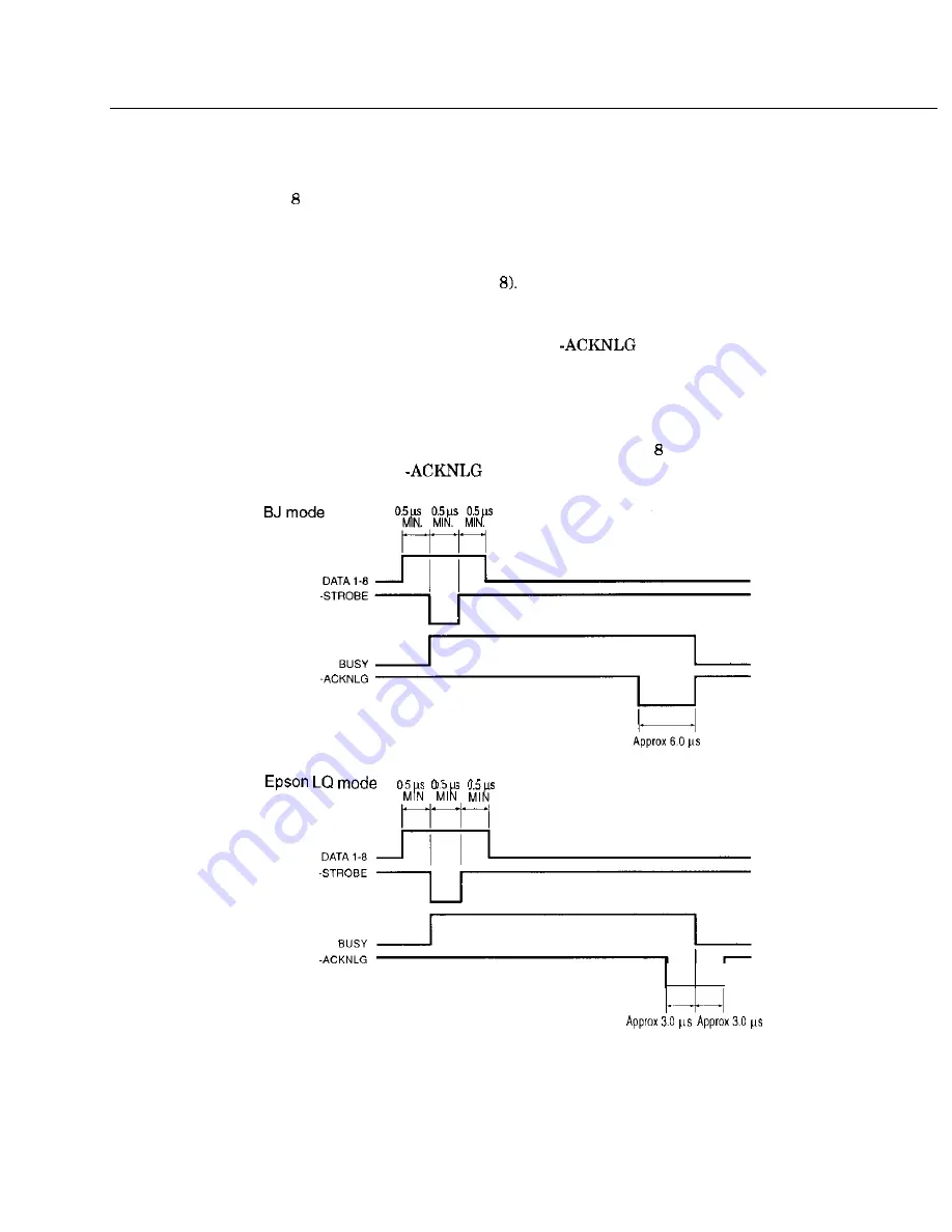
Timing chart
The
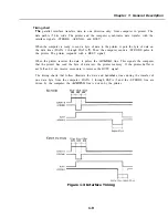
parallel interface transfers data in one direction only: from computer to printer. The
data path is bits wide. The printer and the computer synchronize data transfer with the
interface signals, -STROBE, -ACKNLG, and BUSY.
When the computer is ready to send a byte of data to the printer, it puts the byte of data on
the data lines (DATA 1 through DATA
Then the computer sends a -STROBE pulse to
the printer. The printer responds with a BUSY signal.
When the printer receives the data, it pulses the
line. This signals the computer
that the printer has read the byte of data into the printer memory
If the printer buffer is
not full and it can receive more data, it removes the BUSY signal.
The timing charts that follow illustrate the data and handshake lines during the transfer of
one data byte from the computer. DATA 1 through DATA and the -STROBE line are
driven by the computer; the
line is driven by the printer.
Figure 1-3 Interface Timing
1-9
Summary of Contents for C5000 - MultiPASS Color Inkjet Printer
Page 1: ...MultiPASS C5000 SERVICE MANUAL Canon ...
Page 5: ...REVISION I CONTENT 0 I Original ...
Page 26: ...Chapter 7 General Description 3 1 External View Front View Figure 1 3 External View 1 l 11 ...
Page 27: ...Part 1 Facsimile Rear View Inside the Printer Cover Figure 1 4 External View 2 1 12 ...
Page 28: ...Part 7 Facsimile 3 2 Operation Panel The Operation Panel Document feed lever 0 0 0 0 1 14 ...
Page 34: ...Part 1 Facsimile ...
Page 36: ...Part 7 Facsimile r w Units mm r 0 4 0 0 Figure l 13 Dimensions l 22 ...
Page 65: ...Chapter 1 General Description Waste Ink absorber Figure 1 23 Waste Ink Absorber 1 51 ...
Page 92: ...Part 7 Facsimile Figure 2 18 Printing Signals HQ Mode 2 24 ...
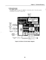
Page 93: ...Chapter 2 Technical Refereno 6 1 Component Block Diagram Figure 2 19 Block Diagram 2 25 ...
Page 150: ...Part 1 Facsimile Figure 3 28 Print Pattern Sample 3 48 ...
Page 184: ...Part 1 Facsimile U Vertical alignment Correction l l l l 3 7 ...


