Chapter General Description
5.3.4
Paper feed section
a)
General precautions
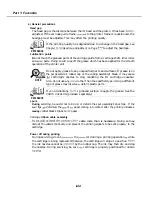
Setting the paper
For fax operations, the user sets the paper size with the
Desktop Manager
for Windows, The unit cannot detect the paper size automatically. Therefore, if the
paper size is altered during servicing, be sure to set it back to the user’s paper size
setting.
A
If the paper size setting does not match the size of the paper installed. One
of the following two operations will be executed:
(A) If the paper size setting is the same or smaller than the actual size of
the paper installed. the following will be executed:
The document will be printed to the length of the paper size that
has been set.
Even if the paper size setting is smaller than the actual paper size,
printing will be executed and no error will result. Depending on the
document, large blank areas may result on the printout.
If the paper size setting is larger than the actual paper size, the
following will be executed:
As with
the document will be printed to fit the length of the paper
size that has
been set. Since the actual
paper size is shorter than the
paper size setting, the document’s contents would be broken up to fit
the paper size setting.
“CHECK PAPER”
will therefore be displayed
and printing will be canceled.
5.3.5 Control boards
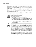
a)
Hardware switch and adjustable
volume
SCNT board’s volume resistor
has been factory-adjusted. Service personnel are
not to alter its setting.
power supply unit’s
has been factory-adjusted.
personnel are not to alter its setting.
Regarding the
switch for servicing, refer to Chapter 3:
Hardware
on Page
3-31.
b) Replacing the SCNT board
The SCNT board stores the user data, service data,
other data. Therefore,
replacing the SCNT board, print out the stored data and
enter this data into the new
SCNT board.
The SCNT hoard
is described in “54.4
board
replacement
on Page l-52.
REFERENCE
Summary of Contents for C5000 - MultiPASS Color Inkjet Printer
Page 1: ...MultiPASS C5000 SERVICE MANUAL Canon ...
Page 5: ...REVISION I CONTENT 0 I Original ...
Page 26: ...Chapter 7 General Description 3 1 External View Front View Figure 1 3 External View 1 l 11 ...
Page 27: ...Part 1 Facsimile Rear View Inside the Printer Cover Figure 1 4 External View 2 1 12 ...
Page 28: ...Part 7 Facsimile 3 2 Operation Panel The Operation Panel Document feed lever 0 0 0 0 1 14 ...
Page 34: ...Part 1 Facsimile ...
Page 36: ...Part 7 Facsimile r w Units mm r 0 4 0 0 Figure l 13 Dimensions l 22 ...
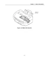
Page 65: ...Chapter 1 General Description Waste Ink absorber Figure 1 23 Waste Ink Absorber 1 51 ...
Page 92: ...Part 7 Facsimile Figure 2 18 Printing Signals HQ Mode 2 24 ...
Page 93: ...Chapter 2 Technical Refereno 6 1 Component Block Diagram Figure 2 19 Block Diagram 2 25 ...
Page 150: ...Part 1 Facsimile Figure 3 28 Print Pattern Sample 3 48 ...
Page 184: ...Part 1 Facsimile U Vertical alignment Correction l l l l 3 7 ...

