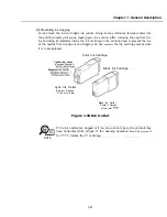
Chapter General Description
5.5.3
Heat protection mechanism
The BJ cartridge head’s aluminum panel becomes hot during printing. It also gets hot if
printing continues even after the ink in the cartridge has been depleted. The aluminum
panel’s temperature is detected by the BJ cartridge’s head temperature sensor.
l
When the carriage is to be moved to the
replacement position, the following
applies:
If the detected temperature exceeds
“WAIT COOLING” is displayed and the
carriage does not move. This is to prevent the
from touching the BJ cartridge’s
aluminum panel. After several minutes
temperature decreases, the cartridge
replacement procedure must be executed again.
l
When a temperature exceeding the standard temperature is detected, the following
applies:
During printing, the printing head temperature is monitored every 50 ms. If the
printing head temperature exceeds
3.5.second wait period is inserted after each
printed line for 20 seconds. This is to allow the printing head to cool. After 20 seconds,
the head temperature is checked. If the temperature has dropped below
normal
printing resumes without any wait period inserted. However, if the head temperature is
still above
the wait period is inserted after each printed line until the printing
head cools
If a head temperature exceeding 100°C is detected for 0.2 sec. during printing, it will be
as BJ head abnormal
error
“CHECK PRINTER
will be
displayed.
printing operation will also stop.
If a head temperature exceeding 100°C is detected for sec. during printing, it will be
deemed as a BJ head temperature sensor error and
“CHECK PRINTER
will be
displayed. The printing operation will also stop.
5.5.4 Overcurrent protection
The fax unit has an overcurrent protection circuit with built-in fuse to prevent an
abnormal
if an ova-current flows to the motors and power supply due
to a driver IC problem, software lockup, or short circuiting.
Protected
Component
Document
motor
Paper feed motor
Carriage motor
Power supply unit
Safety Device
IC protector
on PCNT board
IC protector
on PCNT board
IC protector
on PCNT
Glass-tube current fuse
p r o t e c t i o n
circuit
l-55
Summary of Contents for C5000 - MultiPASS Color Inkjet Printer
Page 1: ...MultiPASS C5000 SERVICE MANUAL Canon ...
Page 5: ...REVISION I CONTENT 0 I Original ...
Page 26: ...Chapter 7 General Description 3 1 External View Front View Figure 1 3 External View 1 l 11 ...
Page 27: ...Part 1 Facsimile Rear View Inside the Printer Cover Figure 1 4 External View 2 1 12 ...
Page 28: ...Part 7 Facsimile 3 2 Operation Panel The Operation Panel Document feed lever 0 0 0 0 1 14 ...
Page 34: ...Part 1 Facsimile ...
Page 36: ...Part 7 Facsimile r w Units mm r 0 4 0 0 Figure l 13 Dimensions l 22 ...
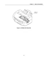
Page 65: ...Chapter 1 General Description Waste Ink absorber Figure 1 23 Waste Ink Absorber 1 51 ...
Page 92: ...Part 7 Facsimile Figure 2 18 Printing Signals HQ Mode 2 24 ...
Page 93: ...Chapter 2 Technical Refereno 6 1 Component Block Diagram Figure 2 19 Block Diagram 2 25 ...
Page 150: ...Part 1 Facsimile Figure 3 28 Print Pattern Sample 3 48 ...
Page 184: ...Part 1 Facsimile U Vertical alignment Correction l l l l 3 7 ...

