5
5
5-3
5-3
Adjustment > Image position adjustment > Leading Edge Non-Image Width
Adjustment > Image position adjustment > Leading Edge Non-Image Width
Image position adjustment
Copy 10 sheets from each pickup position to check that the image margin and non-image
area is within the standard.
• Each cassette
• Pickup tray
If it is not within the standard, go through the following procedures to adjust it.
CAUTION:
If changing the value of service mode item in this adjustment, enter the changed value
in the service label.
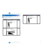
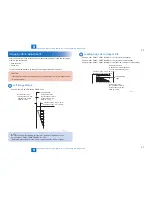
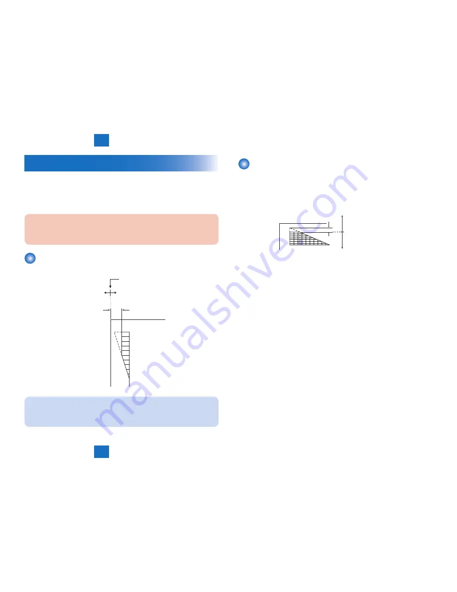
Left Image Margin
Service mode> PRINT> PRINT NUMERIC> 056
10
8
6
5
4
2
0
1st side of copy: 2.5+/-1.5mm
2nd side of copy: 2.5+/-2.0mm
Image left edge
Increase the value.
(an increase of '10' will
increase the margin
width by 1 mm)
Decrease the value.
(a decrease of '10' will
decrease the margin
width by 1 mm)
NOTE:
Be sure to perform the following procedure for right edge margin adjustment.
Service mode > PRINT > PRINT NUMERIC > 055
(Reference target value) 1st side: 0.5mm or larger, 2nd side: 0.5mm or larger
F-5-4
Leading Edge Non-Image Width
Service mode> PRINT> PRINT NUMERIC> 143 (1st side at half speed)
Service mode> PRINT> PRINT NUMERIC> 142 (1st side at normal speed)
Service mode> PRINT> PRINT NUMERIC> 140 (2nd side, common for both speeds)
2 5
4 6 8 101214161820
0
1st side of copy: 2.5+/-1.5mm
2nd side of copy: 2.5+/-1.5mm
Image leading
edge
Decrease the value.
(a decrease of '10' will decrease
the non-image width by 1 mm)
Increase the value.
(an increase of '10' will
increase the non-image
width by 1 mm)
F-5-5
Summary of Contents for Cassette Module-Y1
Page 1: ...6 5 4 3 2 1 Cassette Module Y1 Service Manual Rev 0 ...
Page 6: ... Notes Before it Works Serving Points to Note at Cleaning Safety Precautions ...
Page 8: ...1 1 Product Outline Product Outline Outline Names of Parts ...
Page 10: ...2 2 Technology Technology Basic configuration Controls ...
Page 17: ...3 3 Periodic Servicing Periodic Servicing Periodic Servicing List ...
Page 32: ...5 5 Adjustment Adjustment Outline Image position adjustment ...
Page 36: ...6 6 Installation Installation Installation Installing this Equipment ...
Page 38: ... Service Tools General Circuit Diagram Appendix ...

