Chapter 17
17-8
3. ANALOG
T-17-3
4. CST-STS
T-17-4
5. JAM
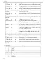
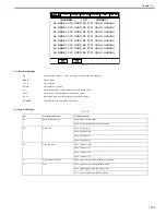
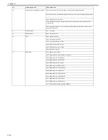
a. Displays jam data
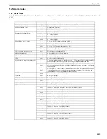
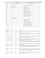
NIB
Displays whether network board is connected.
0: Not connected,
1: Ethernet board connected,
2: Token ring board connected,
3: Ethernet board and token ring board connected
1
NETWARE
Displays whether NetWare firmware is installed.
0: Not installed
1: Installed
1
SEND
Indicates whether SEND function is appended.
0: No SEND function
1: SEND function
1
PDL-FNC1
Display of Enabled PDL (1)
1
PDL-FNC2
Display of Enabled PDL (2)
1
HDD
Display of HDD model name
1
PCI1
Display of PCI1 board name
1
PCI2
Display of PCI2 board name
1
PCI3
Display of PCI3 board name
1
USBH-SPD
Display of USB device connection speed
2
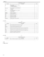
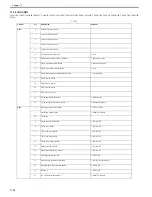
COPIER>DISPLAY>ANALOG
Sub item
Description
level.
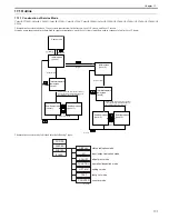
TEMP
Copier's internal temperature (environment sensor) in deg C
1
HUM
Copier's internal humidity (environment sensor) in %RH
1
ABS-HUM
Amount of moisture (environment sensor) in grams
1
FIX-C
Temperature of the fixing roller surface (Detection temperature of the main thermistor)
1
FIX-E
Temperature of the fixing roller surface (Detection temperature of the sub thermistor )
1
FIX-E2
Temperature of the fixing roller surface (Detection temperature of the sub thermistor 2)
1
TEMP2
Temperature in the machine (Environment sensor)
1
HUM2
Humidity in the machine (Environment sensor)
1
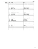
COPIER>DISPLAY>CST-STS
Sub item
Description
level.
WIDTH-MF
Use it to check the width of paper in the manual feed tray (in mm).
2
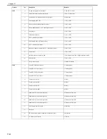
COPIER>DISPLAY>ACC-STS
Sub item
Description
level.
Summary of Contents for CiRC2550
Page 2: ......
Page 27: ...Chapter 1 Introduction ...
Page 28: ......
Page 47: ...Chapter 1 1 18 F 1 14 ON OFF ON OFF ...
Page 70: ...Chapter 1 1 41 5 Turn on the main power switch ...
Page 79: ...Chapter 2 Installation ...
Page 80: ......
Page 85: ...Chapter 2 2 3 Not available in some regions ...
Page 134: ...Chapter 3 Basic Operation ...
Page 135: ......
Page 137: ......
Page 143: ...Chapter 4 Main Controller ...
Page 144: ......
Page 152: ...Chapter 4 4 6 F 4 6 CPU HDD ROM access to the program at time of execution ...
Page 171: ...Chapter 5 Original Exposure System ...
Page 172: ......
Page 203: ...Chapter 6 Laser Exposure ...
Page 204: ......
Page 206: ......
Page 220: ...Chapter 7 Image Formation ...
Page 221: ......
Page 277: ...Chapter 8 Pickup Feeding System ...
Page 278: ......
Page 282: ......
Page 336: ...Chapter 9 Fixing System ...
Page 337: ......
Page 339: ......
Page 357: ...Chapter 10 Externals and Controls ...
Page 358: ......
Page 362: ......
Page 366: ...Chapter 10 10 4 F 10 2 F 10 3 FM1 FM2 FM5 FM8 FM11 FM4 FM3 FM6 FM7 FM9 FM10 ...
Page 375: ...Chapter 10 10 13 F 10 10 2 Remove the check mark from SNMP Status Enabled ...
Page 376: ...Chapter 10 10 14 F 10 11 ...
Page 402: ...Chapter 11 MEAP ...
Page 403: ......
Page 405: ......
Page 452: ...Chapter 12 RDS ...
Page 453: ......
Page 455: ......
Page 464: ...Chapter 13 Maintenance and Inspection ...
Page 465: ......
Page 467: ......
Page 469: ...Chapter 13 13 2 F 13 1 8 9 1 2 3 3 5 6 7 10 11 12 13 14 4 ...
Page 474: ...Chapter 14 Standards and Adjustments ...
Page 475: ......
Page 477: ......
Page 485: ......
Page 486: ...Chapter 15 Correcting Faulty Images ...
Page 487: ......
Page 495: ...Chapter 15 15 4 F 15 2 COLOR M 1 COLOR Y C K 0 ...
Page 569: ...Chapter 15 15 78 F 15 82 J102 J107 J103 J108 J101 J109 J106 J112 J115 J113 J114 J104 J105 ...
Page 570: ...Chapter 16 Self Diagnosis ...
Page 571: ......
Page 573: ......
Page 600: ...Chapter 17 Service Mode ...
Page 601: ......
Page 603: ......
Page 712: ...Chapter 18 Upgrading ...
Page 713: ......
Page 715: ......
Page 746: ...Chapter 19 Service Tools ...
Page 747: ......
Page 749: ......
Page 752: ...APPENDIX ...
Page 774: ......


