Chapter 17
17-61
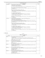
T-17-53
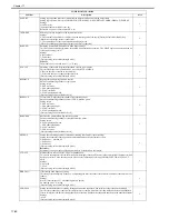
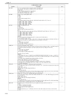
COPIER>OPTION>BODY
Sub item
Description
level.
MODEL-SZ
Used to select standard variable magnification display and ADF document size detection.
Caution!
The setting value takes effect after the main power switch is turned OFF/ON.
Setting values
0: AB (6R5E)
1: INCH (5R4E)
2: A (3R3E)
3: AB/INCH (6R5E)
1
PASCAL
Used to select whether to use the contrast electric potential calculated by automatic gradation compensation (full
compensation) control, and the gradation compensation data.
Caution!
- For printer models, you must always make this setting value 0 at time of installation.
- The setting value takes effect after the power switch is turned OFF/ON.
Setting values
0: Don't use
1: Use
[Factory default/After RAM clear: 1]
1
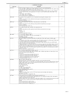
CONFIG
This selects the multiple firmware programs held on the hard disk, and selects the unit's country, language, destination
and sheet size series.
Attention:
The settings take effect after the main power switch has been set to OFF and then back to ON.
Operating procedure
1) Set the unit to the service mode, and select COPIER>OPTION>BODY>CONFIG.
2) Select the items to be selected, and press the "+" and "-" keys.
3) Each time the "+" and "-" key is pressed, the content changes.
4) Display the desired contents, and press the OK key.
5) Set the main power switch to OFF and then back to ON.
Settings: XXYYZZAA
XX: Country (example: JP -> Japan)
YY (*): Language (example: ja -> Japanese)
ZZ (*): Destination (example: 00 -> Canon)
AA: Sheet size series (example: 00 -> AB series)
*: This setting cannot be changed.
1
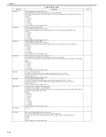
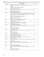
TEMP-TBL
Fixing temperature regulation temperature table change
This is used to adjust the temperature of the temperature regulation for the regular paper (64 to 105g paper) uniform
speed. It improves the hot offset or fixability at the regular paper uniform speed.
Settings
-2:-10 deg C
-1:-5 deg C
0:0 deg C
+1:5 deg C
+2:+10 deg C
[Factory setting/value after clearing RAM: 0]
1
W/SCNR
For copy models, sets whether scanner is present.
Caution!
The setting value takes effect after the main power switch is turned OFF/ON.
Setting values
0: Printer model
1: Model with scanner
Reference:
The setting will automatically change to '1' upon detection of the presence of a scanner (printer model).
1
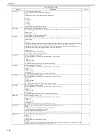
RUI-DSP
Used to select copy function in remote UI.
0: Display copy the screen in remote UI [Factory default/After RAM clear]
1: Don't display copy screen in remote UI
1
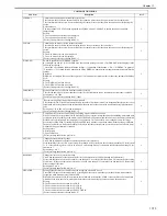
ADJ-LVL
Sets execution mode for image stabilization control performed after preset number of sheets.
Sets execution mode (adjustment set data) for forward/reverse operation of copy or print jobs and image stabilization
control done between sheets.
Reference:
Automatic adjustment control execution mode setting
This makes it possible to reduce the wait time of the users by reducing the menu items to be executed by automatic
adjustment. The automatic adjustment control is executed for Dmax control, Dhalf and ARCDAT.
However, the fluctuations in the image density increase unless the process automatic adjustment is executed from the
user mode.
0: BkDmax c Dhalf and ARCDAT are executed.
1: BkDmax c Dhalf are executed. ARCDAT is not executed.
2: ARCDAT is executed. BkDmax c Dhalf are not executed.
3: Neither BkDmax c Dhalf nor ARCDAT are executed.
[Factory setting/value after clearing RAM: 0]
1
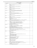
DFDST-L1
A higher setting will increase the level of dust detection (i.e., the machine will be more sensitive in detecting dust, which
if left behind will cause thin lines in the images).
settings range
0 to 255 (0: off)
[Factory default/After RAM clear: 205]
1
DFDST-L2
A higher setting will increase the level of dust detection (i.e., the machine will be more sensitive in detecting dust, which
if left behind will cause thin lines in the images).
settings range
0 to 255 (0: off)
[Factory default/After RAM clear: 155]
1
Summary of Contents for CiRC2550
Page 2: ......
Page 27: ...Chapter 1 Introduction ...
Page 28: ......
Page 47: ...Chapter 1 1 18 F 1 14 ON OFF ON OFF ...
Page 70: ...Chapter 1 1 41 5 Turn on the main power switch ...
Page 79: ...Chapter 2 Installation ...
Page 80: ......
Page 85: ...Chapter 2 2 3 Not available in some regions ...
Page 134: ...Chapter 3 Basic Operation ...
Page 135: ......
Page 137: ......
Page 143: ...Chapter 4 Main Controller ...
Page 144: ......
Page 152: ...Chapter 4 4 6 F 4 6 CPU HDD ROM access to the program at time of execution ...
Page 171: ...Chapter 5 Original Exposure System ...
Page 172: ......
Page 203: ...Chapter 6 Laser Exposure ...
Page 204: ......
Page 206: ......
Page 220: ...Chapter 7 Image Formation ...
Page 221: ......
Page 277: ...Chapter 8 Pickup Feeding System ...
Page 278: ......
Page 282: ......
Page 336: ...Chapter 9 Fixing System ...
Page 337: ......
Page 339: ......
Page 357: ...Chapter 10 Externals and Controls ...
Page 358: ......
Page 362: ......
Page 366: ...Chapter 10 10 4 F 10 2 F 10 3 FM1 FM2 FM5 FM8 FM11 FM4 FM3 FM6 FM7 FM9 FM10 ...
Page 375: ...Chapter 10 10 13 F 10 10 2 Remove the check mark from SNMP Status Enabled ...
Page 376: ...Chapter 10 10 14 F 10 11 ...
Page 402: ...Chapter 11 MEAP ...
Page 403: ......
Page 405: ......
Page 452: ...Chapter 12 RDS ...
Page 453: ......
Page 455: ......
Page 464: ...Chapter 13 Maintenance and Inspection ...
Page 465: ......
Page 467: ......
Page 469: ...Chapter 13 13 2 F 13 1 8 9 1 2 3 3 5 6 7 10 11 12 13 14 4 ...
Page 474: ...Chapter 14 Standards and Adjustments ...
Page 475: ......
Page 477: ......
Page 485: ......
Page 486: ...Chapter 15 Correcting Faulty Images ...
Page 487: ......
Page 495: ...Chapter 15 15 4 F 15 2 COLOR M 1 COLOR Y C K 0 ...
Page 569: ...Chapter 15 15 78 F 15 82 J102 J107 J103 J108 J101 J109 J106 J112 J115 J113 J114 J104 J105 ...
Page 570: ...Chapter 16 Self Diagnosis ...
Page 571: ......
Page 573: ......
Page 600: ...Chapter 17 Service Mode ...
Page 601: ......
Page 603: ......
Page 712: ...Chapter 18 Upgrading ...
Page 713: ......
Page 715: ......
Page 746: ...Chapter 19 Service Tools ...
Page 747: ......
Page 749: ......
Page 752: ...APPENDIX ...
Page 774: ......

