Chapter 9
9-6
Service Mode:
COPIER > OPTION > BODY > P-CGH-TM
Default: 0
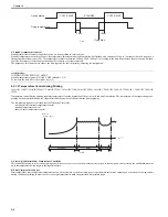
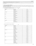
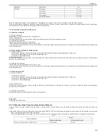
Resets the temperature at which job is restarted and the amount of time required before the restart when the paper size is changed to larger sizes (A4R or wider)
during down-sequence control.
T-9-4
Enter a greater entry if reducing the downtime during paper size switchover is desired. Enter a smaller entry to prevent hot offset immediately after the switchover.
9.2.1.4 Fixing film edge cooling control
0014-5559
Color iR C3380G / Color iR C2880G / Color iR C3380i / Color iR C3380 / Color iR C2880i / Color iR C2880 / iR C3480 / iR C3480i / iR C3080 / iR C3080i / iR
C2550
In the case of continuous prints of the size paper (the width less than A3NC, and as large as A4NC or more), if the sub thermistor detection temperature of the fixing
film reaches to the specified temperature, it executes temperature control to prevent the edge temperature rise by feeding air from the 2 cooling fans to the fixing
film edge. Thanks to this, it prevents film deterioration by heating of the fixing film edge.
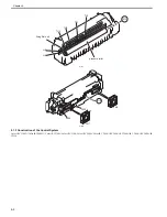
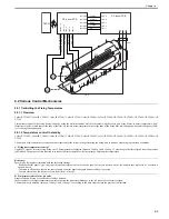
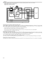
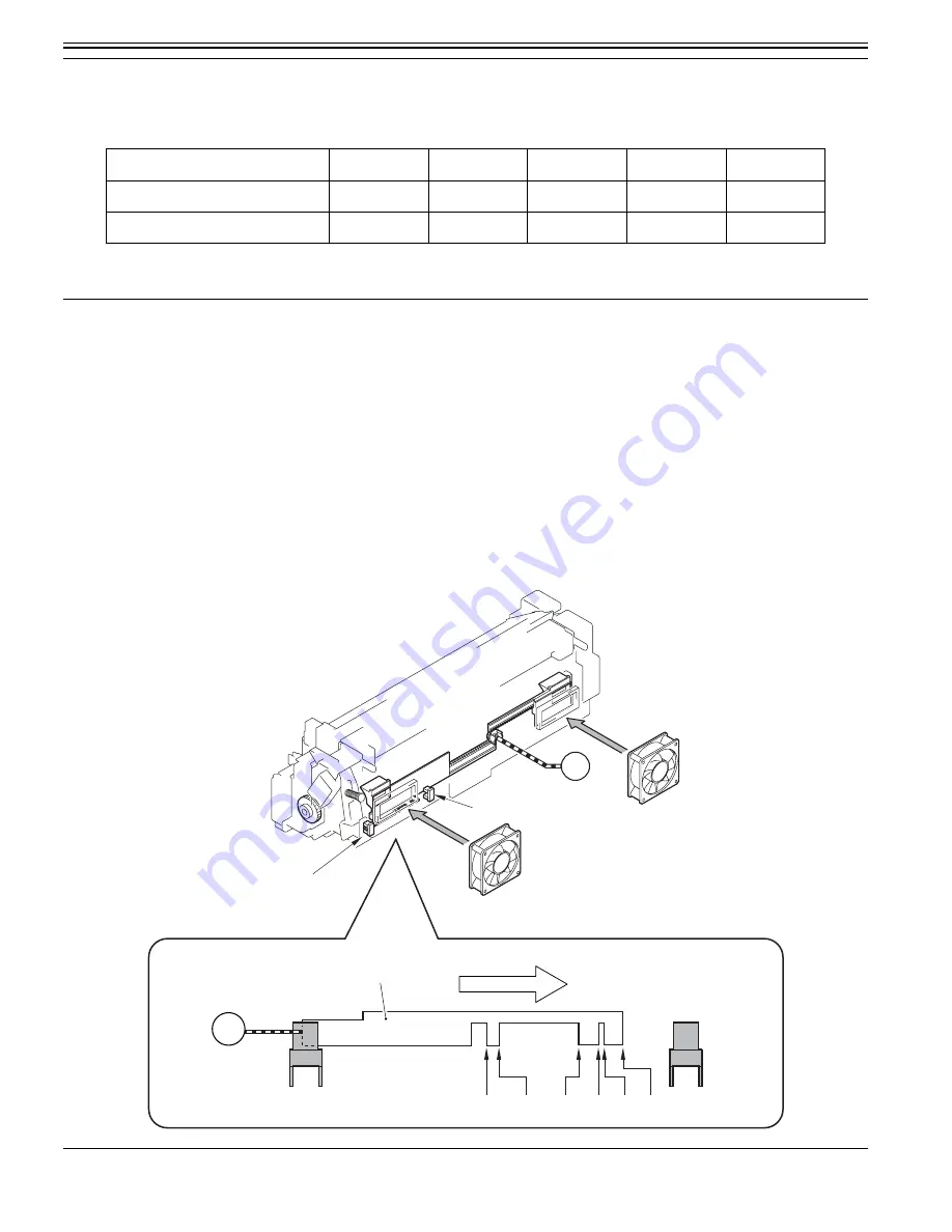
1. Shutter Fan Position Drive Control
The duct that passes air has a shutter mechanism to enable sending air to the ideal area of the fixing film by opening/closing the shutter by 6 steps (from full-close
to full-open) according to the paper size. The shutter opening/closing position that corresponds the paper size has 7-point (A4R, LTRR, B4, EXE, K8, LTR, home
position).
Open/close positions of the shutter is detected by the fan shutter HP sensor (PS28) and fan shutter position sensor (PS29). When sub-thermistor 1 (TH2) detects
temperature listed below, fan shutter motor (M15) is rotated until the fan shutter HP sensor detects the shutter. And then, positive rotation of the fan shutter motor
(M15) is initiated and the shutter is moved to a position corresponds to the paper size chosen. The fan shutter motor is reversely rotated in the last-rotation period,
and the shutter is returned to the home position. If paper size is changed during continuous printing, the shutter is returned to its home position first and then the
shutter is moved to a position corresponds to the paper size chosen.
F-9-6
MEMO:
Entry
-2
-1
0
1
2
Temperature at Return
125
138
150
175
200
Time Before Return
90
90
30
30
30
PS28
M15
A4R LTR-R
B4
EXE K8 LTR
PS29
M15
FM7
PS29
PS28
FM6
Shutter Light-Blocking Plate
direction of movement
Summary of Contents for CiRC2550
Page 2: ......
Page 27: ...Chapter 1 Introduction ...
Page 28: ......
Page 47: ...Chapter 1 1 18 F 1 14 ON OFF ON OFF ...
Page 70: ...Chapter 1 1 41 5 Turn on the main power switch ...
Page 79: ...Chapter 2 Installation ...
Page 80: ......
Page 85: ...Chapter 2 2 3 Not available in some regions ...
Page 134: ...Chapter 3 Basic Operation ...
Page 135: ......
Page 137: ......
Page 143: ...Chapter 4 Main Controller ...
Page 144: ......
Page 152: ...Chapter 4 4 6 F 4 6 CPU HDD ROM access to the program at time of execution ...
Page 171: ...Chapter 5 Original Exposure System ...
Page 172: ......
Page 203: ...Chapter 6 Laser Exposure ...
Page 204: ......
Page 206: ......
Page 220: ...Chapter 7 Image Formation ...
Page 221: ......
Page 277: ...Chapter 8 Pickup Feeding System ...
Page 278: ......
Page 282: ......
Page 336: ...Chapter 9 Fixing System ...
Page 337: ......
Page 339: ......
Page 357: ...Chapter 10 Externals and Controls ...
Page 358: ......
Page 362: ......
Page 366: ...Chapter 10 10 4 F 10 2 F 10 3 FM1 FM2 FM5 FM8 FM11 FM4 FM3 FM6 FM7 FM9 FM10 ...
Page 375: ...Chapter 10 10 13 F 10 10 2 Remove the check mark from SNMP Status Enabled ...
Page 376: ...Chapter 10 10 14 F 10 11 ...
Page 402: ...Chapter 11 MEAP ...
Page 403: ......
Page 405: ......
Page 452: ...Chapter 12 RDS ...
Page 453: ......
Page 455: ......
Page 464: ...Chapter 13 Maintenance and Inspection ...
Page 465: ......
Page 467: ......
Page 469: ...Chapter 13 13 2 F 13 1 8 9 1 2 3 3 5 6 7 10 11 12 13 14 4 ...
Page 474: ...Chapter 14 Standards and Adjustments ...
Page 475: ......
Page 477: ......
Page 485: ......
Page 486: ...Chapter 15 Correcting Faulty Images ...
Page 487: ......
Page 495: ...Chapter 15 15 4 F 15 2 COLOR M 1 COLOR Y C K 0 ...
Page 569: ...Chapter 15 15 78 F 15 82 J102 J107 J103 J108 J101 J109 J106 J112 J115 J113 J114 J104 J105 ...
Page 570: ...Chapter 16 Self Diagnosis ...
Page 571: ......
Page 573: ......
Page 600: ...Chapter 17 Service Mode ...
Page 601: ......
Page 603: ......
Page 712: ...Chapter 18 Upgrading ...
Page 713: ......
Page 715: ......
Page 746: ...Chapter 19 Service Tools ...
Page 747: ......
Page 749: ......
Page 752: ...APPENDIX ...
Page 774: ......

