1-9
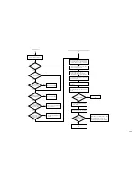
1. Check the transfer charging system.
2. Clean the dust-proofing glass.
3. Clean and check the developing
assembly butting roll.
YES
NO
YES
NO
YES
NO
YES
NO
NO
YES
NO
YES
NO
YES
YES
NO
YES
NO
NO
YES
YES
NO
YES
NO
YES
NO
Conditions
· copy density at '5'
· text/photo mode
Select OPTION>BODY>PASCAL=0
in service mode.
Check the height of
each charging wire.
Clean the charging wires.*
*If the primary charging
wire is soiled, replace it.
Make sample copies using TEST in
service mode for the following:
0. normal image using Test Sheet
1. PGTEST=4 using M mono color
2. PGTEST=4 using C mono color
3. PGTEST=4 using Y mono color
4. PGTEST=4 using Bk mono color
5. PGTEST=10
6. PGTEST=5 DENS 48
7. PGTEST=14 photo mode
(TXPH:1)
Adjusting the Left/Right Density Slope
Correcting Difference in Density
Make a copy of
the Test Sheet.
Is the density different
between front
and rear?
Is the
density different
between front and rear on
the sample copy made
at PGTYPE=
10 or 5?
Is the difference
in density different from
one color to another?
Is the difference in
density gone?
Is the density higher
(darker) at the rear?
Check the coating of toner on the
developing cylinder. Check the
developing assembly butting roll
and the photosensitive drum butting
block. Clean them if soiled with toner.
Turn the adjusting screw
at the front of the primary
charging assembly
counterclockwise.
Execute test printing at
PGTYPE=10 or 5.
Turn the adjusting screw
at the front of the primary
charging assembly
clockwise.
Is the difference in
density gone?
Check to find out if the copyboard
glass is riding over something.
Clean the scanning lamp, reflecting
plate, mirror, standard white plate,
and copyboard glass.
Execute ADJUST>CCD>CCD-ADJ
in service mode.
Is the difference in
density gone?
Check the original scanning lamp.
Is the darkest
area of the test print
made for a 16-gradation
check too light?
Does the density
become lower (lighter)
gradually in continuous
copying mode?
Is the density low (light)
in all colors?
Execute FUNCTION>DPC>DPC
in service mode.
Is the value of
DISPLAY>DPOT>V00-500,
V00-700 normal?
Open the hopper, and insert the
door switch actuator. Check the
temperature and humidity using
DISPLAY>ANALOG>TEMP,
HUM in service mode.
Are the
temperature and humidity
readings normal?
Check the environment sensor.
To [A] of next page.
Check the high-voltage output of
the internal/external static eliminator.
Is the value
of ADJUST>DENS identical
with the value on
the label?
To [B] of next page.
Enter the data once again, and
make 50 copies.
Check the laser shutter and the
laser system.
Reference (normal values)
V00-500: 430 to 570
V00-700: 600 to 800
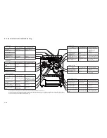
1. Check the insulating sheet of the
transfer blade for scratches and
peeling.
2. Check the shaft of the transfer
drum for play.
3. Check the cable inside the transfer
drum.
D. Image Adjustment Basic Procedure


