2-33
CHAPTER 2 STANDARDS AND ADJUSTMENTS
3
Adjusting the Laser Power
If you replaced the laser scanner unit, laser driver PCB, or laser controller PCB, enter the
values attached to the PCB in service mode (ADJUST>LASER). Attach the label behind the right
front cover for future reference.
If the output of the laser decreases, be sure to adjust the laser power.
•
Laser power checker (FY9-4013)
•
Digital multimeter (CK-0436)
Caution:
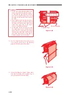
Check the values recorded on the label attached to the right front door.
1) Turn off the power switch.
2) Remove the copyboard glass; then, remove the lens base cover and the laser scanner cover.
3) Turn on the power switch.
4) Open the front left cover. Make sure the front left cover will not close.
5) Remove the left inside cover.
6) Remove the laser power checker inlet cover.
7) Set the laser power checker switch to '2'.
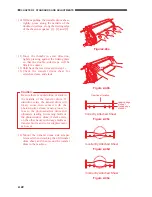
8) Holding the laser power checker [1] so that its light-receiving face is on the right, fit it into the
slot [2].
9) Insert the probe of the laser power checker into the digital multimeter, and set the range to 200
mV.
10) Select FUNCTION>ADJUST>POWER in service mode, and press OK. (laser output)
11) Check the reading of the digital multimeter.
12) Compare the reading (Pmax) indicated on the label and the measurement. If different, turn
VR2 [3] on the laser driver PCB.
Figure 2-64
Figure 2-65
[2]
[1]
[3]


