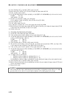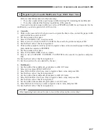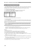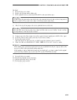
CHAPTER 2 STANDARDS AND ADJUSTMENTS
2-34
Caution:
1. Turn VR2 slowly while monitoring the output of the laser power checker so as to avoid
increasing the laser power excessively. Turning VR2 counterclockwise will decrease the
laser output.
2. Be sure not to exceed the value recorded on the label. Otherwise, the laser diode may
become damaged.
3. Do NOT press the Copy Start key while making adjustments using VR2.
13) Press the Stop key to stop the laser output.
14) Adjust the laser.
4
Adjusting the Laser
Caution:
Be sure to adjust the laser power before starting the following work:
1) Select ADJUST>LASER in service mode.
2) Select T-V00 and enter '255'; then, press OK.
3) Select T-V00-ON, and press OK. (The laser will turn on.) Take notes of the reading (offset). To
stop the laser output, press the Stop key.
4) Select T-V00, and adjust T-V00 so that the following is true: offset value + (0.15 to 0.20 mV)
5) Likewise, adjust T-VFF, PE-V00, P3-VFF-1, P3-VFF-2, P3-VFF-3, and P3-VFF-4. To stop
the laser output, press the Stop key. Study the following table for an idea of optimum output.
6) Press the Reset key to end service mode.
7) Turn off the power switch.
Item
T-V00
T-VFF
P3-V00
P3-VFF-1
P3-VFF-2
P3-VFF-3
P3-VFF-4
Standard (mV)
Offset value + (0.15 to 0.2)
Pmax ×70%
Offset value + (0.1 to 0.15)
Pmax ×45%
Pmax ×55%
Pmax ×65%
Value on label ×70%
Laser ON key
T-V00-ON
T-VFF-ON
P3V00-ON
P3-V1-ON
P3-V2-ON
P3-V3-ON
P3-V4-ON

