CHAPTER 3 EXPOSURE SYSTEM
3-6
COPYRIGHT © 1999 CANON INC. CANON CLC1120/1130/1150 REV.0 MAR. 1999 PRINTED IN JAPAN (IMPRIME AU JAPON)
III.
CONTROLLING THE INTENSITY OF THE
SCANNING LAMP
A. Outline
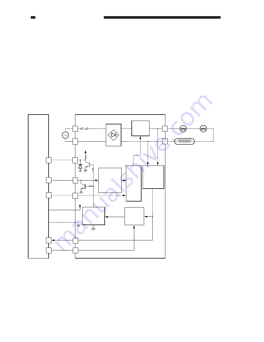
Figure 3-301 shows the circuit that controls the intensity of the scanning lamp (LA2), and has
the following functions:
1.
Turning on/off the scanning lamp.
2.
Finds out whether the scanning lamp is on or not.
3.
Controls the intensity of the scanning lamp (so as to keep the intensity to a specific level
against fluctuations in power voltage).
Figure 3-301
CPU PCB
AC
power
supply
J9
FU1
24V
PWM
1
J10
3
+
-
24V
J2004
J450
4
1
7
10
9
B4
B1
B2
6
TIM-RST
LACNTL
LAON
LAERR
LAON-S*
4
B7
B5
Rectifying
circuit
Lamp
regulator
drive circuit
Error latch
circuit
Switching
circuit
Intensity
control
circuit
Timer
circuit
Lamp
activation
detection
circuit
Activation detection signal
Lamp regulator
Scanner
thermal
switch 1 (TP1)
Scanner
thermal
switch 2 (TP6)
Scanning lamp
(LA2)
Summary of Contents for CLC 1120
Page 6: ......
Page 20: ......
Page 22: ......
Page 48: ......
Page 94: ......
Page 96: ......
Page 114: ......
Page 134: ......
Page 136: ......
Page 152: ......
Page 242: ......
Page 346: ......
Page 374: ......
Page 376: ......
Page 412: ......
Page 452: ......
Page 454: ......
Page 517: ......
Page 881: ......
Page 893: ......
Page 895: ......
Page 899: ......


