COPYRIGHT © 1999 CANON INC. CANON CLC1120/1130/1150 REV.0 MAR. 1999 PRINTED IN JAPAN (IMPRIME AU JAPON)
3-11
CHAPTER 3 EXPOSURE SYSTEM
B. Scanner Drive Assembly
1. Removing the Scanner Drive Motor
1) Remove the rear cover and the rear upper
cover; then, detach the flywheel.
2) Remove the primary charging assembly
fan.
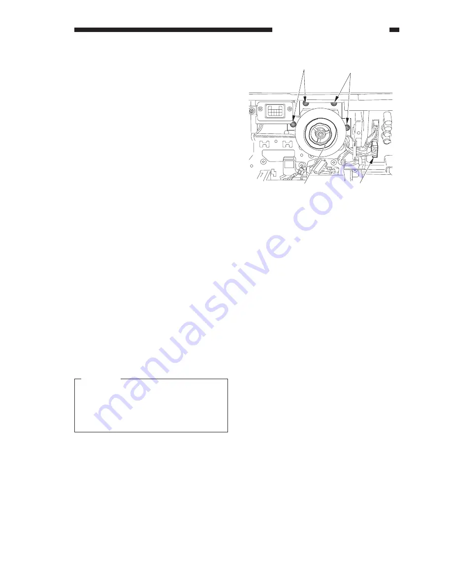
3) Disconnect the connector [1], and remove
the four screws [2]; then, detach the
scanner drive motor [3] together with its
support plate.
4) Remove the two screws, and detach the
scanner drive motor from the support
plate.
Figure 3-407
2. Adjusting the Tension of the Belt
When Mounting the Scanner Drive
Motor
1) Put the belt over the pulley, and tighten
the screw by moving the motor as much as
possible to the right.
Caution:
Take extra care when mounting the
motor so that you will not trap the
scanner cable during the work. (It is a
good idea to push away the scanner
cable when tightening the screw.)
3. Routing the Scanner Cable
Obtain the mirror positioning tool (FY9-
3040-000) when mounting the scanner cable.
1) Remove the copyboard cover.
2) Remove the vertical size plate.
3) Remove the copyboard glass.
4) Remove the control panel.
[1]
[2]
[3]
[2]
Summary of Contents for CLC 1120
Page 6: ......
Page 20: ......
Page 22: ......
Page 48: ......
Page 94: ......
Page 96: ......
Page 114: ......
Page 134: ......
Page 136: ......
Page 152: ......
Page 242: ......
Page 346: ......
Page 374: ......
Page 376: ......
Page 412: ......
Page 452: ......
Page 454: ......
Page 517: ......
Page 881: ......
Page 893: ......
Page 895: ......
Page 899: ......


