CHAPTER 6 IMAGE FORMATION SYSTEM
6-54
COPYRIGHT © 1999 CANON INC. CANON CLC1120/1130/1150 REV.0 MAR. 1999 PRINTED IN JAPAN (IMPRIME AU JAPON)
Caution:
See to it that the removed developing
assembly will remain free of foreign
matter.
Do not place the developing assembly
near the copier and handle the transfer
assembly frame or the photosensitive
drum frame unit above it.
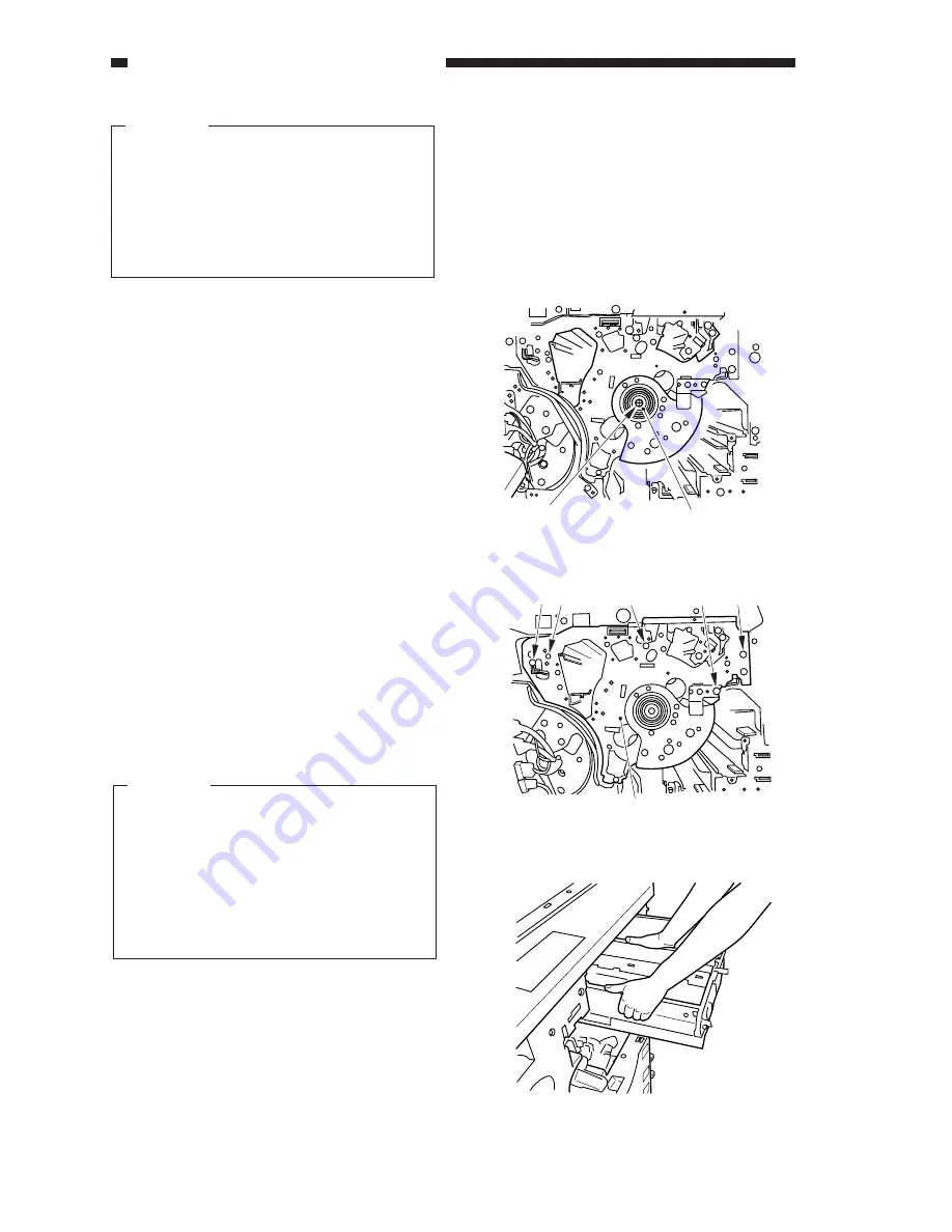
11) Remove the black toner concentration
sensor unit.
12) Remove the screw [5], and detach the
photosensitive drum positioning roll [6].
Figure 6-604
13) Remove the three screws [7]; then, loosen
the two fixing pins [8], and slide out the
photosensitive drum frame unit [9].
Figure 6-605
Caution:
When sliding out the photosensitive
drum frame unit, be sure to work with
extra care so as not to damage the
photosensitive drum.
If contact is made near the front, lift it
slightly to remove. At this time, check
to make sure that the transfer assembly
frame unit is inside the copier.
Figure 6-606
[5]
[6]
[7]
[7]
[7]
[8]
[8]
[9]
Summary of Contents for CLC 1120
Page 6: ......
Page 20: ......
Page 22: ......
Page 48: ......
Page 94: ......
Page 96: ......
Page 114: ......
Page 134: ......
Page 136: ......
Page 152: ......
Page 242: ......
Page 346: ......
Page 374: ......
Page 376: ......
Page 412: ......
Page 452: ......
Page 454: ......
Page 517: ......
Page 881: ......
Page 893: ......
Page 895: ......
Page 899: ......


