CHAPTER 6 IMAGE FORMATION SYSTEM
6-70
COPYRIGHT © 1999 CANON INC. CANON CLC1120/1130/1150 REV.0 MAR. 1999 PRINTED IN JAPAN (IMPRIME AU JAPON)
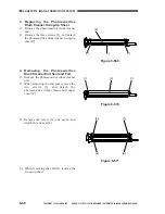
11) Remove the gear [23].
Figure 6-643
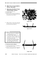
12) Shift the bearings [24] found on both ends
of the developing cylinder in the direction
of the arrow, and pull off the cylinder
[25].
Figure 6-644
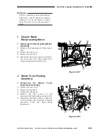
Caution:
While butting the bearing against the
wall X1 of the case, force the sleeve in
the direction of Y and mount the grip
ring Z1, making sure there is no gap.
In this condition, butt the opposite
bearing against the wall X2 of the case,
and mount the grip ring so that the gap
between the roll and the washer is 0.2
±0.1 mm.
Figure 6-645
[23]
[24]
[25]
X1
X2
0.2 0.1mm
Z1
Y
Summary of Contents for CLC 1120
Page 6: ......
Page 20: ......
Page 22: ......
Page 48: ......
Page 94: ......
Page 96: ......
Page 114: ......
Page 134: ......
Page 136: ......
Page 152: ......
Page 242: ......
Page 346: ......
Page 374: ......
Page 376: ......
Page 412: ......
Page 452: ......
Page 454: ......
Page 517: ......
Page 881: ......
Page 893: ......
Page 895: ......
Page 899: ......


