COPYRIGHT © 1999 CANON INC. CANON CLC1120/1130/1150 REV.0 MAR. 1999 PRINTED IN JAPAN (IMPRIME AU JAPON)
7-101
CHAPTER 7 PICK-UP / FEEDING SYSTEM
F. Transfer Drum Cleaner
Locking Motor Assembly
(PM6)
1. Removing the Transfer Drum
Cleaner Locking Motor Assembly
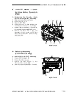
1) Slide out the transfer drum frame.
2) Remove the rear cover.
3) Open the CPU PCB.
4) Remove the screw [1], and disconnect the
external static eliminator connector [2].
5) Remove the two screws [3], and remove
the fixing assembly connector base [4].
6) Remove the three screws [5], and
disconnect the two connectors [6]; then,
detach the transfer drum cleaner locking
motor assembly.
Figure 7-874
[5]
[4]
[3]
[5]
[5]
[6]
[2]
[1]
G. Delivery Assembly
(CLC1120/1130 only)
1. Removing the Delivery Assembly
1) Remove the left upper cover.
2) Remove the delivery cover.
3) Remove the four screws [1], and
disconnect the connector [2].
4) Slide out the delivery assembly to detach.
Figure 7-875
[2]
[1]
Summary of Contents for CLC 1120
Page 6: ......
Page 20: ......
Page 22: ......
Page 48: ......
Page 94: ......
Page 96: ......
Page 114: ......
Page 134: ......
Page 136: ......
Page 152: ......
Page 242: ......
Page 346: ......
Page 374: ......
Page 376: ......
Page 412: ......
Page 452: ......
Page 454: ......
Page 517: ......
Page 881: ......
Page 893: ......
Page 895: ......
Page 899: ......


