COPYRIGHT © 1999 CANON INC. CANON CLC1120/1130/1150 REV.0 MAR. 1999 PRINTED IN JAPAN (IMPRIME AU JAPON)
8-3
CHAPTER 8 FIXING SYSTEM
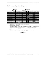
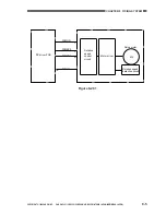
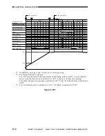
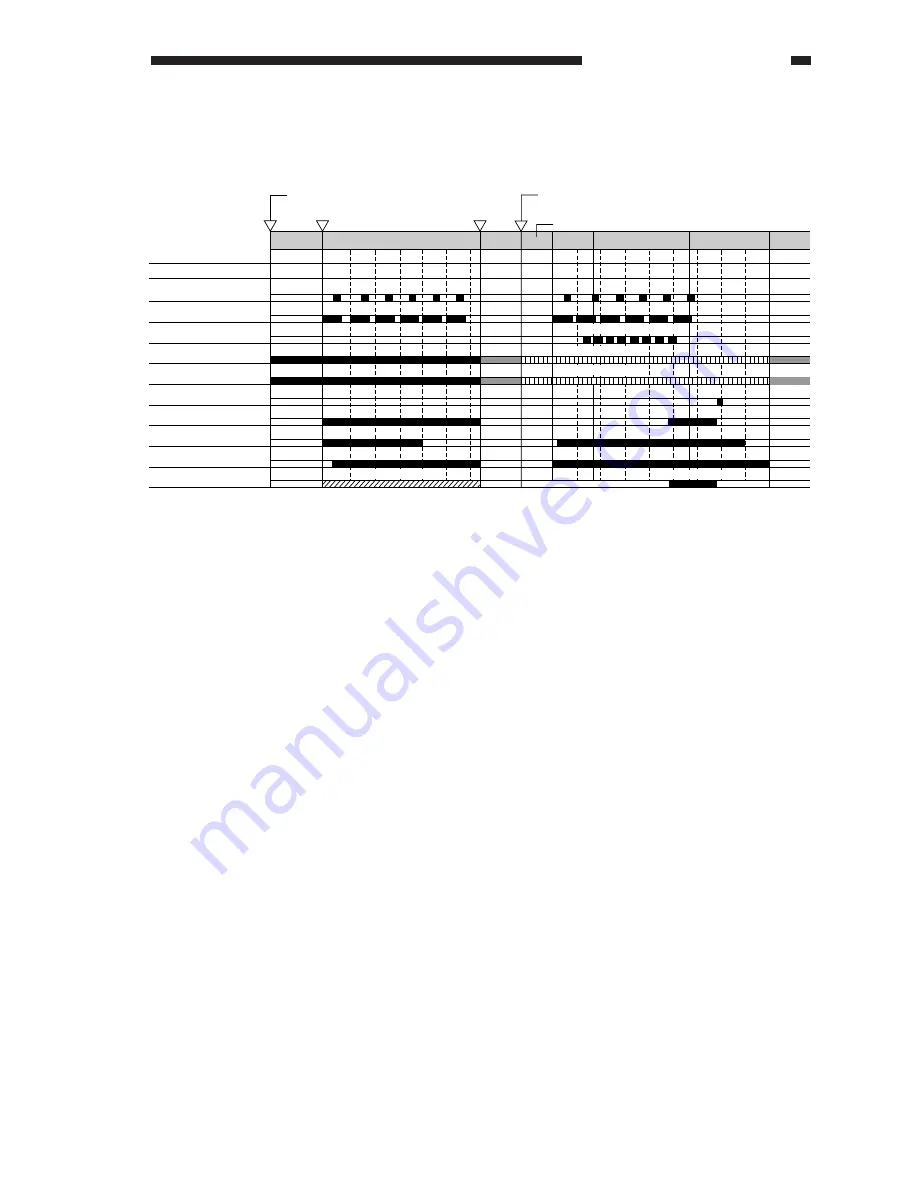
B. Sequence of Operations (fixing system)
WMUP
AINTR
STBY
INTR
1
1
2
2
3
3
4
4
5
6
1
1
2
2
3
3
4
4
5
5
6
6
7
7
COPY
LSTR
DSRDY
75mm/sec
M
Controlled to 158 C
Controlled to 158 C
M
C
C
Y Y Bk Bk
*1
*2
*2
200mm/sec
*3
*3
8
8
9
9
STBY
*3
*3
Photosensitive drum
revolution
Transfer drum revolution
Side A sensor (PS2)
Side B sensor (PS3)
Laser
Main heater (H1)
Sub heater (H2)
Cleaning belt solenoid
(SL1, SL2)
Oil pump (PSP)
Main motor (M4)
Drum motor (M2)
Fixing motor
(M5)
130 C
158 C
Power switch ON
Copy Start key ON
Figure 8-102
*1: If small size, once per copy; for large size, twice per copy.
*2: For normal full color copying.
For 3 hr from the start (if the temperature of the fixing roller is 100°C or less when the
power switch is turned on), controlled to 163°C in the case of full-color copying.
For normal mono-color copying, controlled to 163°C; for 3 hr from the start, controlled to
168°C.
Controlled to 168°C in the case of mono-color copying.
*3: For 3 hr from the start, controlled to 163°C; for others, controlled to 158°C.
Summary of Contents for CLC 1120
Page 6: ......
Page 20: ......
Page 22: ......
Page 48: ......
Page 94: ......
Page 96: ......
Page 114: ......
Page 134: ......
Page 136: ......
Page 152: ......
Page 242: ......
Page 346: ......
Page 374: ......
Page 376: ......
Page 412: ......
Page 452: ......
Page 454: ......
Page 517: ......
Page 881: ......
Page 893: ......
Page 895: ......
Page 899: ......


