COPYRIGHT © 1999 CANON INC. CANON CLC1120/1130/1150 REV.0 MAR. 1999 PRINTED IN JAPAN (IMPRIME AU JAPON)
8-9
CHAPTER 8 FIXING SYSTEM
III.
CONTROLLING THE FIXING TEMPERATURE
A. Controlling the Temperature of the Fixing Roller
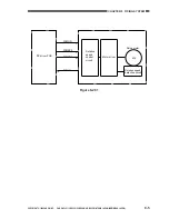
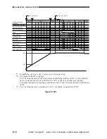
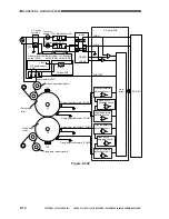
The fixing upper roller and the fixing lower roller are each heated by a fixing heater (main
heater H1, sub heater H2). The surface temperature of the upper roller is monitored by the fixing
upper thermistor 1 (THM1) and that of the lower fixing roller is monitored by the fixing lower
thermistor 3 (THM3) in terms of voltage.
Using voltage readings, the DC-CPU on the CPU PCB causes the fixing upper heater drive
signal (UHON) and the fixing lower heater drive signal (LHON) to go ‘1’ or ‘0’ so as to control the
surface temperature of each roller to a specific level. (See Table 8-301.)
If energy saver mode has been selected in user mode, the surface temperature of the upper roller
and the lower roller is controlled as shown in Table 8-302.
Table 8-301
Note:
The values in parentheses indicate the temperature detected by the thermistor.
table 8-302
Operation
Control temperature
During full-color copying
During mono-color copying
During standby
Upper roller
158°C (156°C)
163°C (161°C)
158°C (156°C)
Lower roller
158°C (156°C)
163°C (161°C)
158°C (156°C)
Saving rate
Recovery time
Control temperature
0%
0 sec
158°C
10%
75 sec
135°C
25%
210 sec
100°C
50%
420 sec
50°C
Summary of Contents for CLC 1120
Page 6: ......
Page 20: ......
Page 22: ......
Page 48: ......
Page 94: ......
Page 96: ......
Page 114: ......
Page 134: ......
Page 136: ......
Page 152: ......
Page 242: ......
Page 346: ......
Page 374: ......
Page 376: ......
Page 412: ......
Page 452: ......
Page 454: ......
Page 517: ......
Page 881: ......
Page 893: ......
Page 895: ......
Page 899: ......


