CHAPTER 9 EXTERNALS / AUXILIARY MECHANISMS
9-6
COPYRIGHT © 1999 CANON INC. CANON CLC1120/1130/1150 REV.0 MAR. 1999 PRINTED IN JAPAN (IMPRIME AU JAPON)
B. Operations
1. 2-Speed Rotation Control
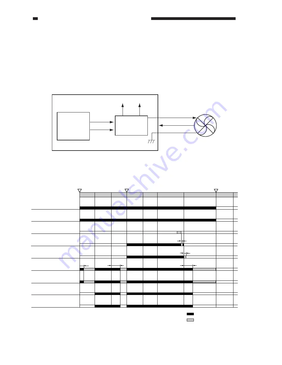
The rotation of some of the fans used in the copier is controlled so that they operate at full speed
(24 V) or half speed (15 V) in response to a switch of voltage by the voltage switching circuit of the
respective fan. (Table 9-401)
If an error occurs in the rotation of a fan, the copier indicates ‘E804’ on the control panel. To
reset the copier, remove the cause, and turn on the power switch. (Table 9-401)
Figure 9-402
R-CPU or
DC-CPU
CPU PCB
Full speed
signal
Half speed
signal
Voltage
switching circuit
Error signal
24V/15V
24V
15V
Fan
2. Sequence of Operations
Figure 9-403
STBY
STBY
COPY
CNTR
DSRDY
AINTR
WMUP
Laser scanner motor cooling fan
(FM4)
Power supply cooling fan 1/2
(FM9/FM13)
Delivery cooling fan (FM11)*1
Delivery cooling fan (FM11)*2
Original exposure system cooling
fan 1/2/3 (FM1/FM14/FM15)
Exhaust fan (FM2)
IP cooling fan (FM7)
Electric unit cooling fan (FM8)
Primary charging assembly fan
(FM3)
Ozone suction fan (FM5)
Toner suction fan (FM6)
Back suction fan (FM16)
Power supply cord mount fan (FM17)
*1: For plain paper or special paper 1 mode; in sync with the fixing motor.
*2: For transparency film or special paper 2 mode.
Power switch
Copy Start key
Power switch
ON
ON
OFF
2 sec
30 sec
4 min
4 min
2 sec
: full speed.
: half speed.
Summary of Contents for CLC 1120
Page 6: ......
Page 20: ......
Page 22: ......
Page 48: ......
Page 94: ......
Page 96: ......
Page 114: ......
Page 134: ......
Page 136: ......
Page 152: ......
Page 242: ......
Page 346: ......
Page 374: ......
Page 376: ......
Page 412: ......
Page 452: ......
Page 454: ......
Page 517: ......
Page 881: ......
Page 893: ......
Page 895: ......
Page 899: ......


