CHAPTER 9 EXTERNALS / AUXILIARY MECHANISMS
9-30
COPYRIGHT © 1999 CANON INC. CANON CLC1120/1130/1150 REV.0 MAR. 1999 PRINTED IN JAPAN (IMPRIME AU JAPON)
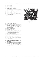
4) Temporarily secure the drum motor
assembly [7] to the copier with seven
screws [8].
Figure 9-733
5) Mount the drum shaft positioning tool [9]
to the photosensitive drum frame unit with
the two screws [10] removed in step 2).
6) Secure the drum motor assembly in place
with seven screws.
7) Remove the drum shaft positioning tool,
slide out the photosensitive frame unit
from the copier; then, mount the unit and
parts removed in steps 1) and 2).
Figure 9-734
[8]
[8]
[8]
[8]
[7]
[8]
[9]
[10]
Summary of Contents for CLC 1120
Page 6: ......
Page 20: ......
Page 22: ......
Page 48: ......
Page 94: ......
Page 96: ......
Page 114: ......
Page 134: ......
Page 136: ......
Page 152: ......
Page 242: ......
Page 346: ......
Page 374: ......
Page 376: ......
Page 412: ......
Page 452: ......
Page 454: ......
Page 517: ......
Page 881: ......
Page 893: ......
Page 895: ......
Page 899: ......


