COPYRIGHT © 1999 CANON INC. CANON CLC1120/1130/1150 REV.0 MAR. 1999 PRINTED IN JAPAN (IMPRIME AU JAPON)
11-53
CHAPTER 11 INSTALLATION
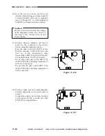
13) Shift bit 6 of the DIP switch [20] (SW2-6)
on the PCB to OFF.
Figure 11-713
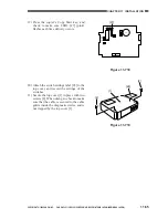
14) Connect the telephone line to the
diagnostic device.
If you are connecting the diagnostic
device on its own, connect the modular
jack cable to the connector LINE [21].
If you are using the extension function of
the diagnostic device, connect the existing
telephone or fax machine to the connector
TEL [22], and then connect the telephone
cable to the connector LINE [21].
Figure 11-714
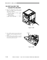
15) Call the service station, and request initial
settings. (Upon reception, LED4 [23]
(red) will start to flash.)
Figure 11-715
LED1 LED2 LED3
2
1
LED5
LED6
LED4
IC6
SW1
SW4
SW3
6
1
BAT1
CN4
1
2
CN3
CN2
12345678
[20]
SW2
LED1 LED2 LED3
2
1
LED5
LED6
LED4
IC6
SW1
SW4
SW3
6
1
BAT1
CN4
1
2
CN3
CN2
SW2
[22] [21]
LED1 LED2 LED3
2
1
LED5
LED6
LED4
IC6
SW1
SW4
SW3
6
1
BAT1
CN4
1
2
CN3
CN2
SW2
[23]
Summary of Contents for CLC 1120
Page 6: ......
Page 20: ......
Page 22: ......
Page 48: ......
Page 94: ......
Page 96: ......
Page 114: ......
Page 134: ......
Page 136: ......
Page 152: ......
Page 242: ......
Page 346: ......
Page 374: ......
Page 376: ......
Page 412: ......
Page 452: ......
Page 454: ......
Page 517: ......
Page 881: ......
Page 893: ......
Page 895: ......
Page 899: ......


