CHAPTER 2 BASIC OPERATION
2-18
COPYRIGHT © 1999 CANON INC. CANON CLC1120/1130/1150 REV.0 MAR. 1999 PRINTED IN JAPAN (IMPRIME AU JAPON)
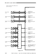
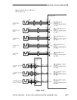
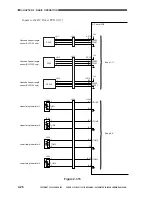
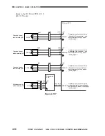
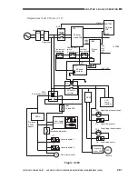
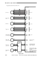
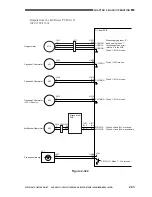
Inputs to the DC Driver PCB (1/13)
Figure 2-307
SJAMD*
POSTTRD
PRETRD
J575
-1
-2
-3
J581
-1
-2
-3
J322
-B9
-B8
-B7
J578
J579
J321
-B3
J1014
-B8
-B4
-B7
-B6
-B5
-A9
-A10
-A11
-B2
-B3
-B8
-B9
-1
-2
-3
-1
-2
-3
-A6
-A7
-A8
J576
-1
-2
-3
J558
-1
-2
-3
J312
J548
-B9
-B10
-B11
J311
J1013
J321
J1014
-B1
-B14
-B10
-B4
-B1
-B2
-B3
J577
-1
-2
-3
J322
+5V
AITOP
BITOP
CITOP
POSTJD
PREJD
SJAMD
BLRMHP
PS8
+5V
PS7
+5V
PS6
+5V
PS5
+5V
PS4
-B6
-B5
-B4
+5V
+5V
PS2
PS3
-A5
-A4
-A3
Side A sensor
Side B sensor
C sensor
Pre-transfer paper
sensor
Post-transfer paper
sensor
Separation sensor
Attraction/transfer
locking cam
HP sensor
Transfer
driver PCB
Registration
path driver
PCB
Transfer
driver PCB
DC driver PCB
When the transfer drum is at the
side A image leading edge, '1'.
(The light-blocking plate is at PS2.)
When the transfer drum is not at the
side B image leading edge, '1'.
(The light-blocking plate is not at PS3.)
See p. 6-3.
When PS5 detects copy paper, '1'.
When PS6 detects copy paper, '1'.
When PS7 detects copy paper, '1'.
(The light-blocking plate is at PS7.)
When the attraction/transfer locking
cam motor is not at the home position,
'1'. Inputs to the DC Driver PCB.
Summary of Contents for CLC 1120
Page 6: ......
Page 20: ......
Page 22: ......
Page 48: ......
Page 94: ......
Page 96: ......
Page 114: ......
Page 134: ......
Page 136: ......
Page 152: ......
Page 242: ......
Page 346: ......
Page 374: ......
Page 376: ......
Page 412: ......
Page 452: ......
Page 454: ......
Page 517: ......
Page 881: ......
Page 893: ......
Page 895: ......
Page 899: ......


