CHAPTER 13 TROUBLESHOOTING
13-198
COPYRIGHT © 1999 CANON INC. CANON CLC1120/1130/1150 REV.0 MAR. 1999 PRINTED IN JAPAN (IMPRIME AU JAPON)
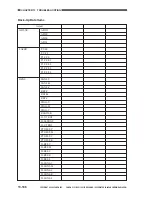
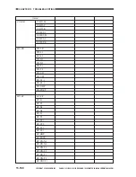
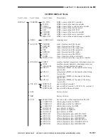
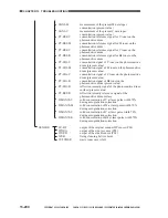
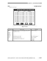
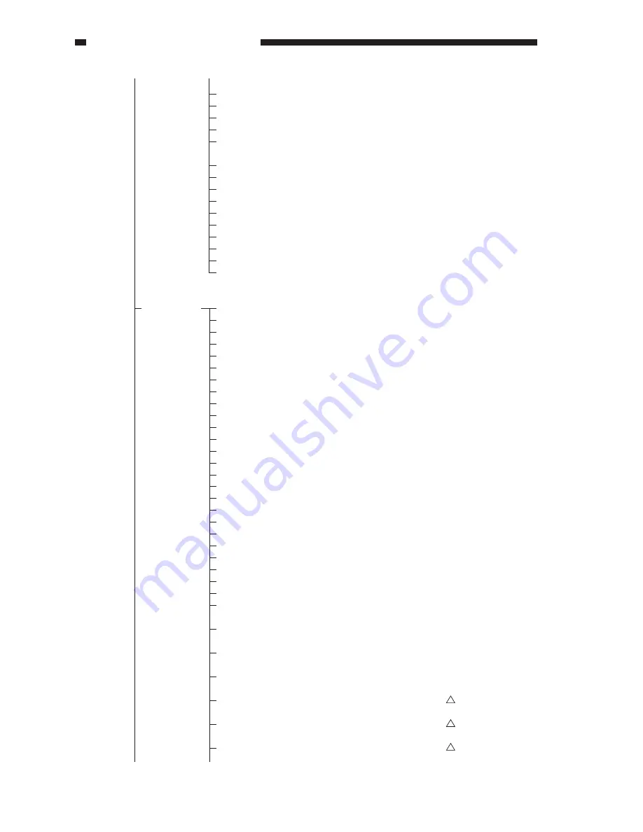
DPOT
GAIN-OB
GAIN-OG
GAIN-OR
CCD-TYPE
METAL
GAIN-EB
GAIN-EG
GAIN-ER
BOF-OB
BOFF-OG
BOF-OR
BOF-EB
BOF-EG
BOF-ER
LAMP-DAT
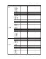
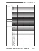
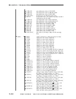
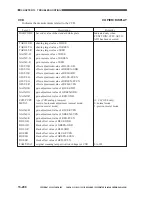
DPOT
V00-Y
V00-M
V00-C
V00-K
VFF-Y
VFF-M
VFF-C
VFF-K
VDC-Y
VDC-M
VDC-C
VDC-K
VG-Y
VG-M
VG-C
VG-K
VCONT-Y
VCONT-M
VCONT-C
VCONT-K
VBACK-Y
VBACK-M
VBACK-C
VBACK-K
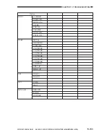
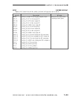
V00-500
V00-700
VFF-500
VFF-700
DV00-500
DVFF-500
DV00-700
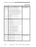
gain adjustment value of LUE-ODD
gain adjustment value of GREEN-ODD
gain adjustment value of RED-ODD
indicates type (CCD/analog processor)
indicates the result of automatic adjustment (normal
mode/precious metal mode)
gain adjustment value for BLUE-EVEN
gain adjustment value for GREEN-EVEN
gain adjustment value for RED-EVEN
black offset value for BLUE-ODD
black offset value for GREEN-ODD
black offset value for RED-ODD
black offset value for BLUE-EVEN
black offset value for GREEN-EVEN
black offset value for RED-EVEN
data value of activation voltage for the scanning
lamp
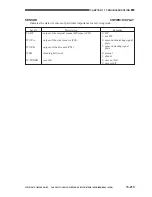
surface potential (V) of the photosensitive drum
setting (V) of Y at laser output 00
setting (V) of M at laser output 00
setting (V) of C at laser output 00
setting (V) of Bk at laser output 00
setting (V) of Y at laser output FF
setting (V) of M at laser output FF
setting (V) of C at laser output FF
setting (V) of Bk at laser output FF
setting (V) of Y for developing bias DC component
setting (V) of M for developing bias DC component
setting (V) of C for developing bias DC component
setting (V) of Bk for developing bias DC component
setting (V) of Y for grid bias
setting (V) of M for grid bias
setting (V) of C for grid bias
setting (V) of Bk for grid bias
setting (V) of Y for target contrast potential
setting (V) of M for target contrast potential
setting (V) of C for target contrast potential
setting (V) of Bk for target contrast potential
setting (V) of Y for de-fogging potential
setting (V) of M for de-fogging potential
setting (V) of C for de-fogging potential
setting (V) of for de-fogging potential
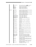
setting of drum surface potential at laser V00 while
the primary charging assembly is at -500 V
setting of drum surface potential at laser VFF while
the primary charging assembly is at -700 V
setting of drum surface potential at laser V00 while
the primary charging assembly is at -500 V
setting of drum surface potential at laser VFF while
the primary charging assembly is at -700 V
dark area potential attenuation (
V) at laser V00
while the drum surface potential is at 500 V
dark area potential attenuation (
V) at laser VFF
while the drum surface potential is at 500 V
dark area potential attenuation (
V) at laser V00
while the drum surface potential is at 700 V
Summary of Contents for CLC 1120
Page 6: ......
Page 20: ......
Page 22: ......
Page 48: ......
Page 94: ......
Page 96: ......
Page 114: ......
Page 134: ......
Page 136: ......
Page 152: ......
Page 242: ......
Page 346: ......
Page 374: ......
Page 376: ......
Page 412: ......
Page 452: ......
Page 454: ......
Page 517: ......
Page 881: ......
Page 893: ......
Page 895: ......
Page 899: ......

