COPYRIGHT © 1999 CANON INC. CANON CLC1120/1130/1150 REV.0 MAR. 1999 PRINTED IN JAPAN (IMPRIME AU JAPON)
2-41
CHAPTER 2 BASIC OPERATION
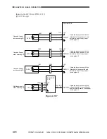
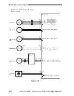
Outputs from the DC Driver PCB (11/15)
Figure 2-330
CL16
J725
-2
-1
+24V
CL18
CL19
J1026
-A14
-A15
J701
J341
-B12
J1017
-B7
MFPUCL
PCFDCL
DVERPCL
FM6
J537
-3
-1
-2
FM11
TNFMON1
J536
TNFMERR
DLFMERR
+24V
FM9
FM13
+24V
J633
-2
-1
J345
-B11
-B12
J645
J708
-3
-1
J1029
-13
-14
DCFMERR
J1707
-1
-2
J1025
-5
-4
J713
-1
-3
-2
J714
-1
-3
-2
-B4
-B6
-B5
J532
-3
-1
-2
J1008
-A3
-A5
-A4
TNFMON2
DLFMON1
DLFMON2
+24V
+24V
+15V
+24V
+15V
+24V
Multifeeder
pickup clutch
Postcard feeder
clutch (100V model
only)
Delivery vertical
path roller clutch
(CLC1150 only)
Toner suction
fan
Delivery cooling
fan
Power supply
cooling fan 1
Power supply
cooling fan 2
Pickup driver
PCB
DC power
supply PCB
DC driver PCB
When '1', CL16 turns on.
When '0', CL18 turns on.
When '0', CL19 turns on.
See p. 9-6.
In response to an error,
returns ERR=1 to the PCB.
See p. 9-6.
In response to an error,
returns ERR=1 to the PCB.
See p. 9-6.
In response to an error,
returns ERR=1 to the PCB.
Summary of Contents for CLC 1120
Page 6: ......
Page 20: ......
Page 22: ......
Page 48: ......
Page 94: ......
Page 96: ......
Page 114: ......
Page 134: ......
Page 136: ......
Page 152: ......
Page 242: ......
Page 346: ......
Page 374: ......
Page 376: ......
Page 412: ......
Page 452: ......
Page 454: ......
Page 517: ......
Page 881: ......
Page 893: ......
Page 895: ......
Page 899: ......


