2-32
CHAPTER 2 NEW FUNCTIONS
COPYRIGHT © 2001 CANON INC.
2000 2000 2000 2000
CANON CLC5000 REV.0 JAN. 2001
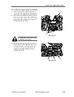
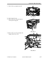
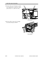
11) Remove the screw [13] from the control
panel support plate, and shift the control
panel [14] by 7 to 8 mm to the front.
[13]
[14]
F02-305-25
12) Remove the five screws [15], and shift
the scanner unit [16] to the left.
[15]
[15]
[16]
F02-305-26
Summary of Contents for CLC 5000
Page 7: ...Main Body Accessory COPYRIGHT 2001 CANON INC 2000 2000 20000 CANON CLC5000 REV 0 JAN 2001 ...
Page 574: ...COPYRIGHT 2001 CANON INC 2000 2000 2000 2000 CANON CLC5000 REV 0 JAN 2001 APPENDIX ...
Page 578: ...COPYRIGHT 2001 CANON INC 2000 CANON CLC5000 REV 0 JAN 2001 A 4 Blank page ...
Page 587: ...Service Mode COPYRIGHT 2001 CANON INC 2000 CANON CLC5000 REV 0 JAN 2001 ...
Page 725: ...Error Code COPYRIGHT 2001CANONINC 2000CANONCLC5000REV 0JAN 2001 ...
Page 727: ...COPYRIGHT 2001 CANON INC 2000 CANON CLC5000 REV 0 JAN 2001 ii CONTENTS Blank page ...

