Chapter 18
18-43
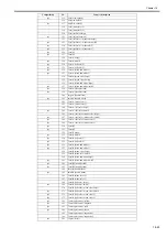
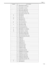
T-18-51
18.2.5.2 OPTION List
0025-8395
Color imageRUNNER C1030 / Color imageRUNNER C1030iF
<BODY>
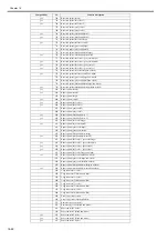
T-18-52
<USER>
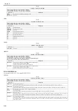
T-18-53
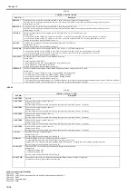
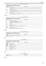
COPIER > OPTION > LCNS-TR
Disabling license transfer
- ST-xxxx, Display of the installation status
Sub item
Description
ST-SEND
Display of the installation status of the Send function when disabling license transfer
Setting value: 0: ON, 1: OFF
[Factory setting value/Value after RAM clearing: 0]
TR-SEND
Display of the 24-digit license key
ST-BRDIM
Display of the installation status of BarDIMM when disabling license transfer
Setting value: 0: ON, 1: OFF
[Factory setting value/Value after RAM clearing: 0]
TR-BRDIM
Display of the 24-digit license key
ST-ERDS
Display of the installation status of the 3rd party extended function for ERDS when disabling license transfer
Setting value: 0: ON, 1: OFF
[Factory setting value/Value after RAM clearing: 0]
TR-ERDS
Display of the 24-digit license key
ST-PCL
Display of the installation status of PCL when disabling license transfer
Setting value: 0: ON, 1: OFF
[Factory setting value/Value after RAM clearing: 0]
TR-PCL
Display of the 24-digit license key
ST-EAM
Display of the installation status of EAM function when disabling license transfer
Setting value: 0: ON, 1: OFF
[Factory setting value/Value after RAM clearing: 0]
OF-EAM
Display of the 24-digit license key
ST-ELA
Display of the installation status of ELA function when disabling license transfer
Setting value: 0: ON, 1: OFF
[Factory setting value/Value after RAM clearing: 0]
OF-ELA
Display of the 24-digit license key
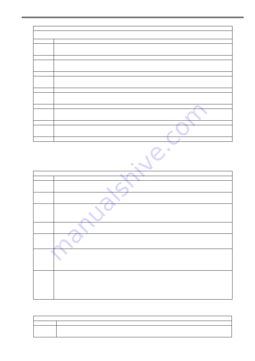
COPIER > OPTION > BODY
Sub item
Description
DFDST-L1
Adjustment of the level of dust detection when DF is used (Correction of an interval between sheets)
When the value is increased, the dust detection level is increased. (This makes it easier to detect the dust causing low-density lines.)
Setting range: 1 to 9999
DFDST-L2
Adjustment of the level of dust detection when DF is used (Detection after a job)
When the value is increased, the dust detection level is increased. (This makes it easier to detect the dust causing low-density lines.)
Setting range: 1 to 9999
TMIC-BK
Switching of the method of correcting the end of TMIC_BK_PASCAL_LUT (high-density area)
Setting value:
0: Correction of the end of BK_LUT for PDL is set to OFF. Correction of the end of Bk_LUT for copy operation is set to OFF.
1: Correction of the end of BK_LUT for PDL is set to ON. Correction of the end of Bk_LUT for copy operation is set to ON.
[Factory setting value/Value after RAM clearing: 1]
AST-SEL
AST-SEL for the change of the advanced smoothing range (AST level SELect)
Setting range: 0 to 3
[Factory setting value/Value after RAM clearing: 2]
TMIC-CMY
Switching of the method of correcting the end of TMIC_PASCAL_LUT (high-density area)
0: Correction of the end of LUT for PDL is set to OFF. Correction of the end of LUT for copy operation is set to OFF.
1: Correction of the end of LUT for PDL is set to ON. Correction of the end of LUT for copy operation is set to ON.
[Factory setting value/Value after RAM clearing: 1]
TMC-SLCT
Switching of the coefficient used for error diffusion correction
Setting value:
0: Small granularity for CMYK
1: Small granularity for CMY, Large granu large stability for K
2: Large granu large stability for CMYK
[Factory setting value/Value after RAM clearing: 0]
IFXEML-Z
Control of the additional function of the attribute flag when printing a message received by email
Setting value:
0: For PDL_Text mode (CardDirect_Gray Correction ODM + Background On)
1: For PDL_Photo mode (CardDirect_Normal ODM + Background Off)
2: For Scan_Photo mode (CardDirect_Normal ODM + Background On)
[Factory setting value/Value after RAM clearing: 0]
* The Text mode is set as default because it is considered that many of the email messages contain documents mixed with text. ODM for CardDirect
is used regardless of PDL or Scan because there is a restriction in terms of input/output color space.
COPIER > OPTION > USER
Sub item
Description
COUNTER1
Selection of the counter type for Counter 1
Setting range: 0 to 999
[Factory setting value/Value after RAM clearing: 101]
Summary of Contents for Color imageRUNNER C1022
Page 2: ......
Page 6: ......
Page 19: ...Chapter 1 Introduction ...
Page 20: ......
Page 93: ...Chapter 2 Installation ...
Page 94: ......
Page 96: ......
Page 111: ...Chapter 3 Basic Operation ...
Page 112: ......
Page 114: ......
Page 119: ...Chapter 4 Main Controller ...
Page 120: ......
Page 122: ......
Page 135: ...Chapter 5 Original Exposure System ...
Page 136: ......
Page 138: ......
Page 151: ...Chapter 6 Original Feeding System ...
Page 152: ......
Page 154: ......
Page 170: ......
Page 171: ...Chapter 7 Laser Exposure ...
Page 172: ......
Page 174: ......
Page 184: ......
Page 185: ...Chapter 8 Image Formation ...
Page 186: ......
Page 188: ......
Page 222: ......
Page 223: ...Chapter 9 Pickup and Feed System ...
Page 224: ......
Page 259: ...Chapter 10 Fixing System ...
Page 260: ......
Page 262: ......
Page 268: ...Chapter 10 10 6 ...
Page 279: ...Chapter 11 External and Controls ...
Page 280: ......
Page 311: ...Chapter 12 e Maintenance imageWARE Remote ...
Page 312: ......
Page 314: ......
Page 323: ...Chapter 12 12 9 F 12 27 ...
Page 349: ...Chapter 13 Maintenance and Inspection ...
Page 350: ......
Page 352: ......
Page 354: ......
Page 355: ...Chapter 14 Measurement and Adjustments ...
Page 356: ......
Page 358: ......
Page 361: ...Chapter 15 Correcting Faulty Images ...
Page 362: ......
Page 364: ......
Page 385: ...Chapter 16 Error Code ...
Page 386: ......
Page 388: ......
Page 399: ...Chapter 16 16 11 ...
Page 400: ......
Page 401: ...Chapter 17 Special Management Mode ...
Page 402: ......
Page 404: ......
Page 411: ...Chapter 17 17 7 ...
Page 412: ......
Page 413: ...Chapter 18 Service Mode ...
Page 414: ......
Page 492: ......
Page 493: ...Chapter 19 Upgrading ...
Page 494: ......
Page 496: ......
Page 500: ...Chapter 19 19 4 3 Click Next F 19 4 4 Select a USB connected device and click Next F 19 5 ...
Page 501: ...Chapter 19 19 5 5 Click Start F 19 6 6 Click Yes F 19 7 Download will be started F 19 8 ...
Page 504: ...Chapter 19 19 8 4 Select a USB connected device and click Next F 19 12 5 Click Start F 19 13 ...
Page 506: ...Chapter 19 19 10 ...
Page 507: ...Chapter 20 Service Tools ...
Page 508: ......
Page 510: ......
Page 514: ......
Page 515: ...Appendix ...
Page 516: ......
Page 532: ......
Page 533: ...Oct 29 2010 ...
Page 534: ......


