COPYRIGHT© 2000 CANON INC.
2000 2000 2000
ColorPASS-Z40e/Z20e REV.0 AUG. 2000
CHAPTER 4 DISASSEMBLY/ASSEMBLY
4-16
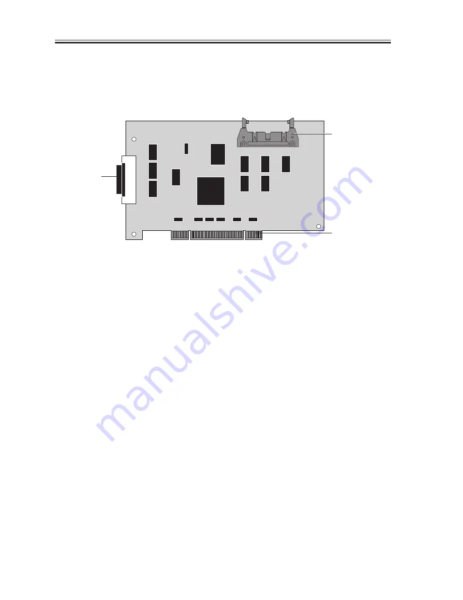
5.4 UIB Board
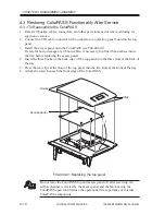
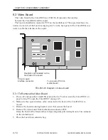
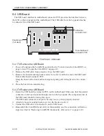
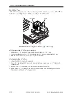
The UIB board installed in motherboard connector PCI3 provides the interface between
the LCD on the top panel and the motherboard. The UIB cable from the top panel attaches
to connector J4 on the UIB board.
F04-504-01 UIB board
5.4.1 To Remove the UIB Board
1. Power off and open the ColorPASS as described in “To shut down the ColorPASS” on
page 4-4 and “To open the ColorPASS” on page 4-5.
2. Remove the UIB cable from connector J4 on the UIB board.
3. Remove the board mounting bracket screw from slot 4 and then remove the UIB board
from motherboard connector PCI3.
Grasp the board at the front and back edge and gently pull it straight out of its connec-
tor.
4. Place the board in an antistatic bag.
5.4.2 To Replace the UIB Board
1. Reseat the UIB board in connector PCI3 on the motherboard. Make sure that the parallel
connector on the board extends through slot 4 in the back panel. The component side of
the UIB board should be facing the copier.
The UIB board connector is keyed to fit only one way when properly oriented.
2. Attach the board mounting bracket screw to the bracket in slot 4.
3. Connect the UIB cable to connector J4 on the UIB board.
4. Reassemble the ColorPASS and verify its functionality (see the connection verification
steps described in “Restoring ColorPASS functionality after service” on page 4-10).
UIB cable
connector (J4)
Parallel port
(not used)
To motherboard
connector PCI3

