background image

PUB.CE-IE-430

0803AB0.1

CANON ELECTRONICS INC. 2003

PRINTED IN JAPAN

CANON ELECTRONICS INC.

1248, SHIMOKAGEMORI, CHICHIBU-SHI, SAITAMA 369-1892, JAPAN

CANON U.S.A. INC.

ONE CANON PLAZA, LAKE SUCCESS, N.Y.11042, U.S.A.

CANON CANADA INC.

6390 DIXIE ROAD, MISSISSAUGA, ONTARIO L5T 1P7, CANADA

CANON EUROPA N.V.

BOVENKERKERWEG 59-61, P.O.BOX 2262, 1180 EG AMSTELVEEN, THE NETHERLANDS

CANON LATIN AMERICA, INC.

703 WATERFORD WAY, SUITE 400 MIAMI, FLORIDA 33126, U.S.A.

CANON AUSTRALIA PTY. LTD.

1 THOMAS HOLT DRIVE, NORTH RYDE, SYDNEY. N.S.W, 2113. AUSTRALIA

CANON SINGAPORE PTE. LTD.

79 ANSON ROAD #09-01/06, SINGAPORE 079906

CANON HONGKONG COMPANY LTD.

9/F., THE HONG KONG CLUB BUILDING, 3A CHATER ROAD, CENTRAL, HONG KONG.
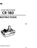
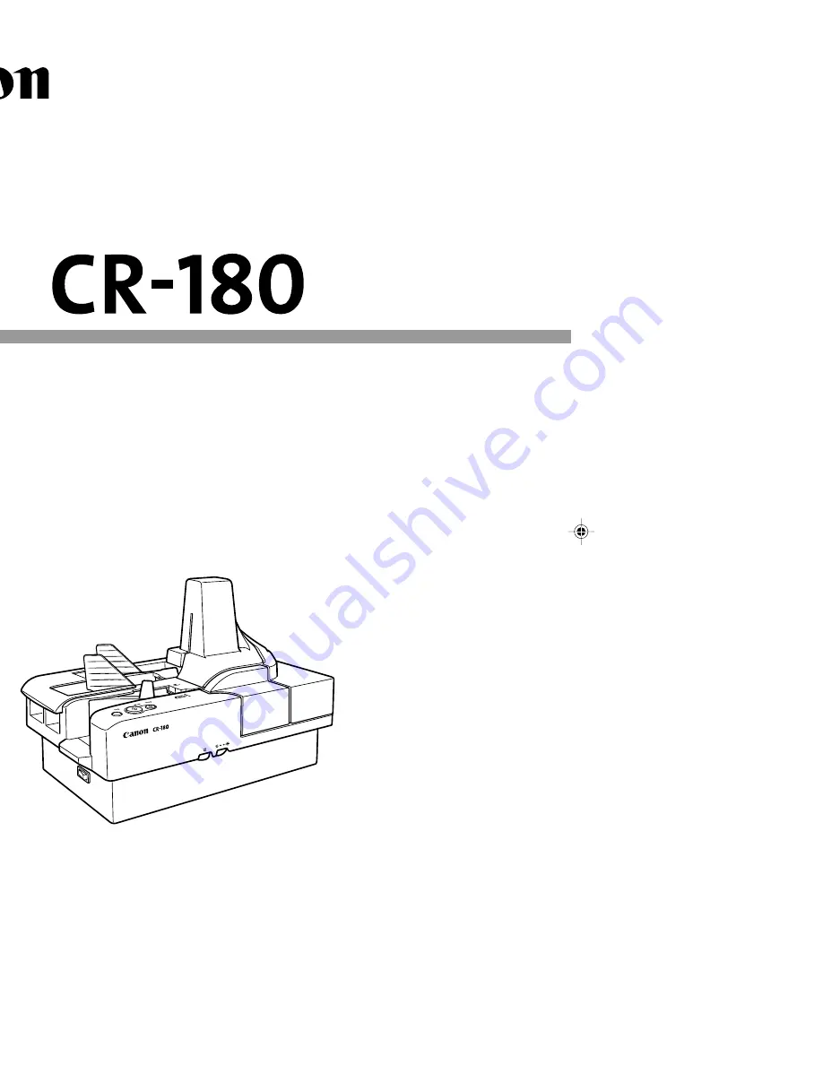
CANON CHECK READER

INSTRUCTIONS

Please read this manual before operating this unit. After you finish
reading this manual, store it in a safe place for future reference.

*CE-IE-430*

 COVER (HARD)-E

03.8.21, 5:22 PM

1

Summary of Contents for CR-180

Page 1: ...CANON CHECK READER INSTRUCTIONS fore operating this unit After you finish t in a safe place for future reference ...

Page 2: ......

Page 3: ...y 90 days from the date you purchased the same as evidenced by a receipt or otherwise The limited warranty does not apply if the failure of the diskette resulted from accident abuse or misapplication of the SOFTWARE and shall not extend to anyone other than the original user of the SOFTWARE CANON CANON S AFFILIATE THEIR DISTRIBUTOR OR DEALER DISCLAIMS ALL IMPLIED WARRANTIES INCLUDING ANY WARRANTY ...

Page 4: ......

Page 5: ...ur safety and contain extremely important information Failure to observe the instructions provided in a warning could result in death or serious injury to yourself or your co workers Caution notices are also provided for your safety and contain important information Failure to observe the instructions provided in a caution notice could result in serious injury to yourself or your co workers or dam...

Page 6: ...ration Before Use 2 1 Checking Your Operating Environment 16 2 2 Connecting the Scanner to a Computer 17 SCSI Connections 17 SCSI Cards 17 Connecting the SCSI Cable 18 Setting the SCSI ID 18 USB Connections 19 USB 2 0 Interface Cards 19 Connecting the USB Interface Cable 20 Connecting the Power Cord 20 2 3 Turning ON and OFF the Power 21 Turning ON the Power 21 Recognizing the Scanner 22 Turning O...

Page 7: ...nts 38 Types of Documents 38 Placing Documents 39 4 2 Document Feeding and Scanning 41 Scan Procedure 41 Manual Feeding Bypass Mode 43 Chapter 5 Troubleshooting 5 1 When the Scanner Is Not Recognized 46 SCSI Connections 46 USB Connections 47 5 2 Clearing Paper Jams 48 5 3 Feeding Trouble 50 5 4 When the Scanned Image Is Not Normal 52 Chapter 6 Maintenance 6 1 Daily Cleaning 54 Cleaning the Main Un...

Page 8: ...4 Specifications 67 Scanner Specifications 67 Exterior Dimensions 68 Index 69 ...

Page 9: ...he scanner Never use flammable aerosol products near the scanner Before you clean the scanner turn the power OFF and disconnect the power cord from the power outlet To clean the scanner s exterior use a firmly wrung cloth moistened slightly with water or mild detergent Never use any type of volatile solution such as alcohol benzene or paint thinner If you hear strange sounds detect smoke or abnorm...

Page 10: ...k the core leads damage the power cord and cause a fire or electrical shock Keep the area around the power outlet clear of all obstacles so you can disconnect the power cord easily at all times Never spill water or volatile solutions alcohol benzene paint thinner into the scanner Doing so may cause a fire or electrical shock When the scanner is not being used for a long time disconnect the power c...

Page 11: ...t and fumes Dust and cigarette fumes adversely affect the components inside the scanner Near running water a heat source water vapor or in an area such as a laboratory exposed to ammonia gas paint thinner or other volatile chemicals Places subject to vibration and strong shock Places subject to rapid changes in temperature or humidity Condensation occurring inside the scanner may impair image qual...

Page 12: ... your local power company Never place an object on top of the power cord or step on the power cord Never bundle the power cord or wrap the cord around an object such as a table leg Do not tug on the power cord When you remove the power cord grip it by the plug head Keep the area around the power outlet free of obstacles Carrying When you move the CR 180 hold it firmly with both hands and carry it ...

Page 13: ...er describes the features of the scanner what comes packaged in the box and the names and functions of parts on the scanner 1 1 Features of the CR 180 10 1 2 Packaging What Is in the Box 12 1 3 Part Names 13 Front View 13 Rear View 14 Connectors 14 ...

Page 14: ...million scans Compact size 10 7 H x 15 7 W x 9 5 D 271 mm H x 399 mm W x 242 mm D Supports black and white binary and grayscale output Reads MICR characters A magnetic head is used to scan MICR characters that have been printed with magnetic ink or toner Supports OCR Optical Character Recognition Character images such as E13B OCR A OCR B and check writer are recognized as characters by the OCR fun...

Page 15: ... scanner detects double fed documents Drop out color This function enables drop out scanning of a specific color in the document Imprinter is standard equipment An imprinter mechanism to print text on documents as they are scanned comes standard equipped with the scanner The imprinter s ink cartridge is not included and must be purchased separately See About the Ink Cartridge on p 25 ...

Page 16: ...ery item you have removed from the box If any items are missing contact your local authorized Canon dealer 1 The power cord varies according to the country of purchase 2 For the United States and Canada only CR 180 Power Cord 1 Document Feed Guide Warranty Card 2 Instructions This Manual Setup Disc Jogger Support ...

Page 17: ...c Head for MICR Reads MICR characters that have been printed with magnetic ink Maintenance Cover Open this cover to clear paper jams or to clean the scanner Ink Cartridge Ink cartridge is not included Purchase the ink cartridge separately See About the Ink Cartridge on p 25 Bypass manual Mode Button Use this button when you want to scan multiple documents continuously or documents that stick toget...

Page 18: ...ating and causing a fire never block the air vents on the back of the scanner Connectors DIP switch This switch is for setting the SCSI ID See Setting the SCSI ID on p 18 SCSI connector Connect a half pitch 50 pin SCSI cable See Connecting the SCSI Cable on p 18 USB connector Connect a Hi Speed USB 2 0 compatible cable See Connecting the USB Interface Cable on p 20 CAUTION ...

Page 19: ...nvironment 16 2 2 Connecting the Scanner to a Computer 17 SCSI Connections 17 USB Connections 19 Connecting the Power Cord 20 2 3 Turning ON and OFF the Power 21 Turning ON the Power 21 Recognizing the Scanner 22 Turning OFF the Power 24 2 4 Preparing the Ink Cartridge 25 About the Ink Cartridge 25 Adjusting the Print Position 25 ...

Page 20: ... the following operating systems For SCSI Microsoft Windows 95 OSR2 Microsoft Windows 98SE Microsoft Windows Me Microsoft Windows NT 4 0 Workstation SP6 Microsoft Windows 2000 Professional SP4 Microsoft Windows XP SP1 For USB Microsoft Windows 98SE Microsoft Windows Me Microsoft Windows 2000 Professional SP4 Microsoft Windows XP SP1 Either an ISIS compatible or a TWAIN compatible application that ...

Page 21: ...s See SCSI Cards below SCSI cable The scanner s SCSI connector is a half pitch 50 pin connector Check the shape of the connector on your computer s SCSI card or on the SCSI device connected to your computer and prepare a SCSI cable that is compatible with your operating environment SCSI Cards Be sure to use one of the recommended SCSI cards when connecting the SCSI cable to the scanner The recomme...

Page 22: ...nect the SCSI cable make sure that the scanner and the computer are turned OFF Do not connect both SCSI and USB interface cables at the same time SCSI Connector USB Connector cannot be connected at the same time Setting the SCSI ID Set the SCSI ID using the DIP Dual Inline Package switch located on the left side of the SCSI connector Push the DIP switches down to turn them ON and push them up to t...

Page 23: ...low Recommended USB 2 0 interface cards Manufacturer Adaptec Product USB 2 Connect 2000LP AUA 2000 USB 2 Connect 3100 AUA 3100LP USB 2 Connect 5100 AUA 5100 USB 2 Connect for Notebooks AUA 1420 Be sure to follow the installation procedure in your computer s operation manual when installing the USB 2 0 interface card in your computer Use the most recent USB 2 0 driver provided by Adaptec or Microso...

Page 24: ... Never grasp the plug when your hands are wet Never plug the scanner into a multiplug power strip Never bundle or tie the power cord around itself or another object Connect the plug securely into the power source Use only the power cord and plug provided with the scanner Before you connect the power cord be sure to turn OFF the power switch Be sure to connect the scanner to an AC 220 240V 50 60 Hz...

Page 25: ...D continues to flash there is a problem with the scanner Turn OFF the power and contact your local retailer or a Canon service department If you hear strange sounds detect smoke or abnormal heat sense a vibration or smell odd odors around the scanner turn OFF the power immediately and disconnect the power cord from the power outlet Call for service immediately Failure to do so may cause a fire 2 T...

Page 26: ...suming that D is assigned to your CD ROM drive and then click OK 5 Click Finish If you are using Windows 98SE the Add New Hardware Wizard dialog box appears 1 Click Next 2 Select Search for the best driver for your device Recommended and then click Next 3 Insert the setup disc into the computer s CD ROM drive 4 Select Specify a location type D INF assuming that D is assigned to your CD ROM drive a...

Page 27: ...c location Advanced and then click Next 3 Select Search for the best driver in these locations and then select Search removable media floppy CD ROM to clear the check mark Select Include this location in the search Type D INF assuming that D is assigned to your CD ROM drive and then click Next 4 Click Continue Anyway in the Hardware Installation dialog box Although a message appears indicating tha...

Page 28: ...ess the power switch OFF Turn OFF the power to the computer if you are using a SCSI cable to connect the scanner Wait at least 10 seconds before turning the scanner back ON For your safety disconnect the power plug from the power outlet if you are not using the scanner for a long period of time CAUTION Important ...

Page 29: ... separately as shown below Compatible ink cartridges Hewlett Packard ink cartridge model numbers C6602A black C6602B blue C6602G green C6602R red For details on installing the ink cartridge see Replacing the Ink Cartridge on p 63 Adjusting the Print Position You can adjust the print position to three different levels 1 Remove the top cover 2 Press the open button and pull the maintenance cover ope...

Page 30: ...cates the distance from the bottom edge of the document to the center of the text Adjustment Line Top 1 6 40 mm from the bottom edge of the document Middle 1 4 36 mm from the bottom edge of the document Bottom 1 3 32 mm from the bottom edge of the document 4Close the maintenance cover in the order shown in the diagram below 5Carefully replace the top cover If the top cover is not firmly in place t...

Page 31: ...ility and ISIS TWAIN driver 3 1 About the Software 28 3 2 Installing the Software 29 Installing the Scanning Utility 29 Installing the ISIS TWAIN Driver 30 3 3 How to Use the Software 32 Starting and Closing the Scanning Utility 32 How to Use the ISIS TWAIN Driver 33 3 4 Uninstalling the Software 34 ...

Page 32: ...is installed after you install the utility software ISIS TWAIN driver This scanner driver should be used with ISIS Image and Scanner Interface Specification compatible or TWAIN Technology Without Any Interested Name compatible software Install it only if it is required The ISIS TWAIN driver provided with the scanner does not necessarily operate all ISIS compatible or TWAIN compatible applications ...

Page 33: ...he dedicated scanner driver is installed after the Scanning Utility has been installed 1 Turn ON your computer and log on to Windows Be sure to log on as the Administrator if your system is Windows NT 4 0 Workstation Windows 2000 Professional or Windows XP 2 Insert the setup disc into the CD ROM drive This manual assumes that D is assigned to your CD ROM drive 3 Click Start and then select Run The...

Page 34: ...SIS TWAIN driver is installed C Windows PixTran C Windows System pix dll The names of the Windows and Windows System folders are different depending on which Windows operating system you are using The names of the above folders are representative and should be replaced by the name of the folder used in your operating system 1 Turn ON your computer and start Windows Be sure to log on as the adminis...

Page 35: ...nd then select Run The screen the appears depends on which Windows operating system you are using 4 Enter D Driver setup exe in the Open field and then click OK Installation starts 5 Follow the instructions on the screen to complete the installation ...

Page 36: ...This section describes the procedure for using the Scanning Utility Read the Help file in Scanning Utility for more information Starting the Scanning Utility 1 Click Start point to Programs then click Scanning Utility for CR 180 Click All Programs then Scanning Utility for CR 180 if your Operating System is Windows XP 2 Start the Scanning Utility The basic operation of the Scanning Utility is note...

Page 37: ... How to Use the ISIS TWAIN Driver The explanation on how to use the ISIS TWAIN driver is in the ISIS TWAIN driver help file To view the help file click Start point to Programs click Canon Document Scanner and then click Canon CR 180 Help 3 3 How to Use the Software ...

Page 38: ...ws NT 4 0 Workstation Windows 2000 Professional or Windows XP The dialog boxes and button names in Windows XP are different from the ones used in this manual Refer to the Windows XP Help and Support Center to uninstall the software 1 Click Start point to Settings and click Control Panel 2 Double click the Add Remove Programs icon The Add Remove Programs Properties dialog box appears Important ...

Page 39: ...ll the Canon Driver for CR 180 If you uninstall the ISIS TWAIN driver select the Canon CR 180 ISIS TWAIN Driver 4 The Confirm File Deletion dialog box appears If you selected Scanning Utility for CR 180 the above dialog box appears 5 Click Yes and the uninstaller starts Follow the instructions on the screen to finish uninstalling the software 3 4 Uninstalling the Software Important ...

Page 40: ...36 ...

Page 41: ...ibes precautions regarding documents that can be handled on this scanner and scanning operations 4 1 Documents 38 Types of Documents 38 Placing Documents 39 4 2 Document Feeding and Scanning 41 Scan Procedure 41 Manual Feeding Bypass Mode 43 Scanning ...

Page 42: ...rly or the pencil may rub off onto the rollers and stain subsequent documents Before you scan this kind of document make a copy and then scan the copy After scanning a document written in pencil or some other soft writing material be sure to clean the scanning rollers See Cleaning the Scanning Glass and Rollers on p 55 If you scan thin paper in the Duplex mode the ink printed on the back side may ...

Page 43: ...ound may cause errors in automatic size detection 4 1 Documents Placing Documents Note the following points when placing documents on the scanner Place the front of the document toward you Do not exceed the load limit mark when placing documents in the document tray This may cause feeding errors or paper jams A maximum of 200 documents can be loaded at one time Each eject pocket can hold the same ...

Page 44: ...40 Chapter 4 Document Feeding and Scanning If you place long documents move the stopper to the edge of the document in the document tray Otherwise this may cause a paper eject error Stopper ...

Page 45: ...bjects become entangled immediately disconnect the power plug from the power outlet Check the paper stack and remove all clips staples pins or any other type of metal or plastic fastener These objects may cause damage to the document a paper jam or a scanner malfunction CAUTION Scan Procedure 1 Carefully align the edges of the document 2 Place the first page of the document facing you and place th...

Page 46: ...f various sizes align the leading edges of all the documents with the entry point of feeding The jogger vibrates for 10 seconds and then stops Press one of the operation buttons to stop the jogger If the documents are large the documents may fall over while they are vibrating If this happens attach the jogger support to prevent the documents from falling over 4 Instruct scanning to start from the ...

Page 47: ...ockets according to the separation conditions that have been set Manual Feeding Bypass Mode Use the Bypass manual mode to scan duplicate forms which have sticky edges or documents that have a rough surface Feed these documents one by one and press Bypass Mode button For duplicate forms load the side with the sticky edges toward the feeding entry point Document Feed Guide Flapper Separates document...

Page 48: ......

Page 49: ...ibes the problems that might occur in the CR 180 and how to remedy them 5 1 When the Scanner Is Not Recognized 46 SCSI Connections 46 USB Connections 47 5 2 Clearing Paper Jams 48 5 3 Feeding Trouble 50 5 4 When the Scanned Image Is Not Normal 52 ...

Page 50: ...it If you can see one of these refer to the SCSI card s operator s manual to reset the SCSI card Windows NT 4 0 Workstation Click Start Settings Control Panel open the SCSI adapter dialog box and check if the SCSI card is being recognized correctly If it is not recognized correctly refer to the SCSI card s operator s manual to reset the SCSI card Windows 2000 Professional Click Start Settings Cont...

Page 51: ...I ID is used for other SCSI devices Remedy Check the SCSI ID of all connected SCSI devices and make sure that the same SCSI ID is not set for two or more devices Reset the SCSI IDs if the same SCSI ID is set Cause Another SCSI device is valid as a terminator Remedy Cancel the SCSI device terminator that is connected between the CR 180 and the computer The CR 180 must be at the end of the daisy cha...

Page 52: ...u may be injured unexpectedly For example the paper edges may cut your fingers or the document may be damaged Remove all jammed sheets of paper Paper scraps left inside the scanner may cause a paper jam or malfunction 1 Remove the top cover 2 Press the open button and pull the maintenance cover open to the right and left 3 Remove the paper that has jammed CAUTION ...

Page 53: ...49 5 5 2 Clearing Paper Jams 4 Close the maintenance cover in the order shown in the diagram below 5 Carefully replace the top cover ...

Page 54: ...eed error to occur Scan one sheet at a time in the Bypass manual mode See Manual Feeding Bypass Mode on p 43 Dirty or worn rollers inside the scanner may cause a paper jam Clean the rollers if they are dirty See Cleaning the Scanning Glass and Rollers on p 55 Worn rollers must be replaced Contact your dealer or Canon service representative The separation roller gap is too wide Adjust the separatio...

Page 55: ...side with the MICR characters face up in the document tray Other Causes Some of the MICR characters are scratched or missing Splattered MICR ink or toner may also be the problem Condition The imprinter is not printing correctly missing imprint dots Cause and Remedy Ink is clogged in the ink jet nozzle Clean the ink jet nozzle Cleaning the ink jet nozzle is recommended before using the CR 180 See C...

Page 56: ...d at all the brightness may be set too high If the scanned image appears dark the brightness may be set too low Also check the settings on the driver and the software application The driver or application does not run correctly If the document cannot be scanned correctly even if the scan conditions are adjusted the driver or the application may not be functioning correctly Reinstall the driver or ...

Page 57: ...ain the scanner 6 1 Daily Cleaning 54 Cleaning the Main Unit 54 Cleaning the Scanning Glass and Rollers 55 Cleaning the Magnetic Heads 58 Cleaning the Ink Heads and Ink Absorber 60 6 2 Maintenance 63 Replacing the Ink Cartridge 63 Adjusting the Separation Roller Gap 66 ...

Page 58: ...ner with any kind of organic solvent such as alcohol benzene or paint thinner This may cause a fire and electrical shock or cause the exterior of the scanner to disfigure or disclolor Never spray mild detergent or water directly on the scanning glass The spray could penetrate below the glass and contaminate the internal light source and lenses Cleaning the Main Unit Wipe the scanner with a firmly ...

Page 59: ...canned documents clean the scanning glass or rollers Clean the scanning glass and rollers regularly 1 Remove the top cover 2 Press the open button and pull the maintenance cover open to the right and left If you notice paper dust in the feed path when you open the maintenance cover clean it out with a cotton swab Important ...

Page 60: ... too narrow for your fingers Rollers in positions i to 2 are turned by the roller in position 3 Turn the roller in position 3 to wipe the rollers Open the scanning unit to clean the rollers in positions y to 1 4 Push down the lock lever to release the lock on the scanning unit q and then open the scanning unit w 5 Use cotton swabs that are commercially available to clean the entire scanning glass ...

Page 61: ...Close the maintenance covers in the order shown in the diagram below 8 Carefully replace the top cover If paper jams and double feeds two papers being fed at the same time still occur after cleaning the rollers the rollers may be worn The rollers need to be changed Contact your local dealer or a Canon service representative Important Lock Lever ...

Page 62: ...ailable audio head cleaner 1 Press the open button and pull the maintenance cover open to the right and left If you notice paper dust in the feed path when you open the maintenance cover clean it out with a cotton swab 2 Use a commercially available audio head cleaner to clean the magnetic heads The magnetic heads are located in the positions shown in the diagram below Magnetic Heads Important ...

Page 63: ...59 6 6 1 Daily Cleaning 3 Close the maintenance covers in the order shown in the diagram below ...

Page 64: ...use the text to appears as scratched Clean the area around the ink heads and the ink absorber periodically 1 Remove the top cover 2 Press the open button and pull the maintenance cover open to the right and left If you notice paper dust in the feed path when you open the maintenance cover clean it out with a cotton swab Ink Head Important ...

Page 65: ...hem with a clean dry cloth 4 Remove the ink cartridge For more information see Replacing the Ink Cartridge on p 63 5 Use a cotton swab to remove the ink from around the ink jet nozzle 6 Insert the ink cartridge For more information see Replacing the Ink Cartridge on p 63 Ink Absorber Ink Cartridge 6 1 Daily Cleaning ...

Page 66: ...ance Note 7 Close the maintenance covers in the order shown in the diagram below 8 Carefully replace the top cover If the top cover is not firmly in place the ink cartridge is not installed properly Check the ink cartridge ...

Page 67: ...e printed text becomes scratchy or faint even if you have cleaned the ink jet nozzle Replace the ink cartridge according to the following procedure below Use a Hewlett Packard ink cartridge See About the lnk Cartridge on p 25 1 Remove the top cover 2 Press the open button and pull the maintenance cover open to the right and left 6 2 Maintenance Note ...

Page 68: ... lever and lift up the cartridge 4 Bend the lock lever to the left lever and remove the ink cartridge 5 Bend the lock lever down and insert the new ink cartridge Reposition the lock lever and make sure that the ink cartridge is securely in place Important Lock Lever ...

Page 69: ...the ink cartridge into place 7 Close the maintenance covers in the order shown in the diagram below 8 Carefully replace the top cover If the top cover is not firmly in place the ink cartridge is not installed properly Check the ink cartridge Note 6 2 Maintenance ...

Page 70: ...rn the adjustment dial to move the paper smoothly into the separation roller gap 3 While one sheet of paper is fed into the separation roller gap adjust the adjustment dial so that the second sheet of paper does not feed into the separation roller gap 4 Remove the paper from the document tray and close the shutter Do not use the adjustment dial any other time except when adjusting the separation r...

Page 71: ... 120 g m2 feed capacity Interface SCSI III Hi Speed USB 2 0 Other functions Automatic paper size detection Paper thickness and double feed detection Dropout color Emboss enhancement Dimensions 10 7 H x 15 7 W x 9 5 D 271 mm H x 399 mm W x 242 mm D Weight Approximately 13 9 lb 6 3 kg Power requirement AC 120V 60 Hz or AC 220 240V 50 60 Hz Power consumption 120 V model 220 240 V model Scanning 0 6A ...

Page 72: ...68 Exterior Dimensions Units inches units in parenthesis are millimeters 10 7 271 mm 5 5 140 6 mm 7 1 180 1 mm 15 7 399 mm 9 5 242 mm 18 8 477 mm with the eject stopper open 15 7 398 7 mm Specifications ...

Page 73: ...er 60 Ink cartridge 13 25 63 Ink jet nozzle 63 Installation location 7 ISIS TWAIN driver 28 33 J Jog button 42 Jogger support 13 42 L Load limit mark 39 M Magnetic head 58 Magnetic head for MICR 13 Maintenance 63 Maintenance cover 13 N Number of pages loaded 39 O Operating environment 16 Operation buttons 13 P Power cord 12 20 Power cord connector 14 Power supply 8 Power switch 13 Print position a...

Page 74: ...ow to use the software 32 Specifications Specifications for the scanner 67 T Top cover 13 Troubleshooting 46 Turning OFF the power 24 Turning ON the power 21 U Unpacking the scanner 12 USB connections 19 47 USB 2 0 driver 16 USB interface cable 20 Interface cards 19 Operating systems 16 USB connector 14 Index ...

Page 75: ......

Page 76: ......

Reviews: