CHAPTER 5 TOROUBLESHOOTING
5-28
COPYRIGHT © 1999 CANON INC.
CANON DADF-B1 REV.0 APR. 1999 PRINTED IN JAPAN (IMPRIME AU JAPON)
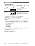
C. Using the DIP Switch
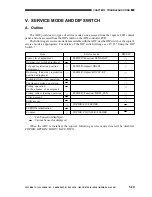
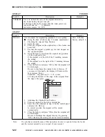
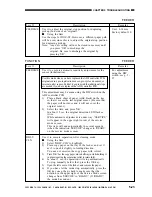
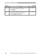
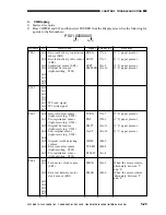
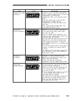
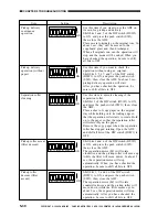
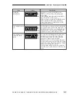
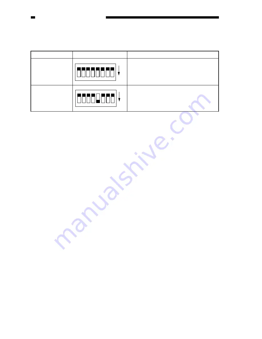
The following table shows the functions of the DIP switch (DSW1) on the ADF controller PCB.
Item
Setting
Description
n
Adjusting the Sensor Level
Perform the following to adjust the sensor level using the DIP switch:
1) Shift bit 4 of the DIP switch to ON, and press the push switch.
2) Close the reversal delivery cover, and place a black sheet of paper over the last original sensor.
(Make sure that the paper does not cover the original sensor, i.e., the Original Set LED will not
turn on.)
3) Open the pickup unit cover once, and then close it. (In about 3 sec, sensor adjustment will start.)
4) In several seconds, the original detection LED will flash twice, and then remain on. At this time,
check the state of the sensor by referring to LED1 and LED2 on the DF controller PCB.
The number of times LED1 flashes (at 300-msec intervals) indicates the sensor number. It flashes
at intervals of 300 msec, remains off for 2 sec, and repeats the sequence. The following shows
how each sensor may be identified:
1: reversal outlet sensor
2: pre-registration sensor
3: original sensor
4: last original sensor
If LED2 remains on, the sensor in question is normal. If it remains off, the sensor in question is
faulty.
5) To move to the next sensor, press the push switch. (With each press, you can move in the
following sequence: 1 -> 2 -> 3 -> 4 -> 1 ->.
6) When all is done, shift bit 5 of the DIP switch to ON, and check to make sure that the Original Set
LED has turned off.
7) Shift all bits of the DIP switch to OFF.
Normal operation
Sensor level
adjustment
When all bits are at OFF, normal operation
will be simulated.
Use it to adjust the level of sensors: last
original sensor, original sensor, pre-
registration sensor, reversal outlet sensor.
O
F
F
1
2
3
4
5
6
7
8
ON
O
F
F
1
2
3
4
5
6
7
8
ON

