background image

COPYRIGHT  © 1999 CANON INC.

CANON DADF-B1 REV.0 APR. 1999 PRINTED IN JAPAN (IMPRIME AU JAPON)

5-29

CHAPTER 5  TROUBLESHOOTING

Item

Setting

Description

Original tray width
adjustment

Registration
position adjustment

Duplexing
registration

Adjustment
(pickup delivery)

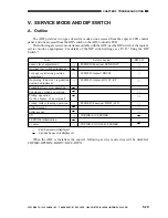
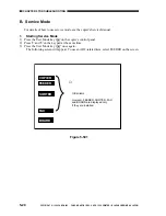
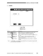
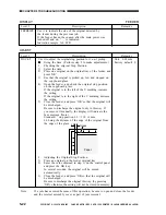
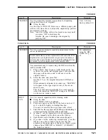
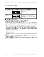
Shift bits 3 and 4 of the DIP switch (DSW1)
to ON. Adjust the original tray to A4 (for A/B
configuration) or LTR (for inch
configuration); then, press the push switch
(SW1).
Adjust the original tray to A4R (for A/B
configuration) or LTRR (for inch
configuration); and, press the push switch
once gain.
Lastly, press the push switch (SW1) once
again, and shift all bits to OFF.

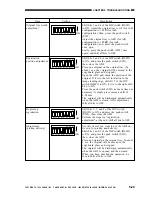
Shift bits 1 and 4 of the DIP switch (DSW1)
to ON, and press the push switch (SW1);
then, close the ADF.
Place one original on the original tray. (In
about 3 sec, the original will be moved to the
copyboard glass and stopped.)
Open the ADF, and check the position of the
original. If it is to the left in relation to the
image leading edge, shift bit 5 of the DIP
switch (DSW1) to ON; if it is to the right, shift
bit 6 to ON.
Press the push switch (SW1) as many times as
necessary. A single press causes a shift of
0.34 mm.
The original will be discharged automatically
when the ADF is closed. After adjustment,
shift all bits to OFF.

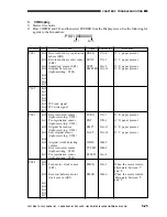
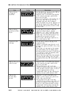
Shift bits 1, 3, and 4 of the DIP switch
(DSW1) to ON, and press the push switch
(SW1); then, close the ADF.
Perform the steps for "registration
adjustment"; at the end, shift all bits to OFF.

Use this item if you want to use the ADF on
its own for pickup and delivery.
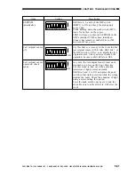
Shift bits 1 and 5 of the DIP switch (DSW1)
to ON, and press the push switch (SW1);
then, close the ADF.
Place an original on the original tray. In about
3 sec, the original will be moved to the
copyboard glass and stopped.
The original will be discharged automatically
when the ADF is opened and then closed.
When you have checked the operation, be
sure to shift all bits to OFF.

O

F

F

1

2

3

4

5

6

7

8

ON

O

F

F

1

2

3

4

5

6

7

8

ON

O

F

F

1

2

3

4

5

6

7

8

ON

O

F

F

1

2

3

4

5

6

7

8

ON

Summary of Contents for DADF-B1

Page 1: ...COPYRIGHT 1999 CANON INC CANON DADF B1 REV 0 APR 1999 PRINTED IN JAPAN IMPRIME AU JAPON FY8 13G6 000 REVISION 0 APR 1999 DADF B1 ...

Page 2: ... OTHER PRINTED MATTER ANY QUESTIONS REGARDING INFORMATION CONTAINED HEREIN SHOULD BE DIRECTED TO THE COPIER SERVICE DEPARTMENT OF THE SALES COMPANY THIS DOCUMENT IS INTENDED FOR ALL SALES AREAS AND MAY CONTAIN INFORMATION NOT APPLICABLE TO CERTAIN AREAS COPYRIGHT 1999 CANON INC Printed in Japan Imprimé au Japon Use of this manual should be strictly su pervised to avoid disclosure of confidential i...

Page 3: ... construction and how its parts may be disassembled assembled and adjusted Chapter 4 Maintenance and Servicing provides tables of periodically replaced parts and consumables durables and scheduled servicing charts Chapter 5 Troubleshooting provides tables of maintenance inspection standards adjustments and problem identification image fault malfunction Appendix contains a general timing chart and ...

Page 4: ...als 2 32 G Detecting an Original Jam 2 43 H Alarm Detection 2 47 I Power Supply 2 50 I BASIC CONSTRUCTION 3 1 A External Covers 3 1 B Removing the Feed Belt Unit 3 4 C ADF Controller PCB 3 5 II DRIVE SYSTEM 3 6 A Removing the Pickup Unit 3 6 B Removing the Separation Motor M1 3 6 C RemovingtheFeedMotor M2 3 7 D Reversal Delivery Unit 3 8 E Removing the Reversal Delivery Motor M3 3 9 III FEEDING SY...

Page 5: ...tors Solenoids and Sensors 5 12 B PCBs 5 14 IV VARIABLE RESISTORS VR LIGHT EMITTING DIODES AND CHECK PINS BY PCB 5 15 A ADF Controller PCB 5 15 B Sensor PCBs 5 16 C Indicator PCB 5 18 V SERVICE MODE AND DIP SWITCH 5 19 A Outline 5 19 B Service Mode 5 20 C Using the DIP Switch 5 28 VI SELF DIAGNOSIS 5 32 A ADF Self Diagnosis 5 32 A GENERAL TIMING CHART A 1 B SIGNALS AND ABBREVIATIONS A 5 C GENERAL ...

Page 6: ...RIME AU JAPON CHAPTER 1 GENERAL DESCRIPTION I FEATURES 1 1 II SPECIFICATIONS 1 2 III NAMES OF PARTS 1 4 A External View 1 4 B Cross Section 1 4 IV OPERATIONS 1 5 A Original Set Indicator 1 5 B Making Copies 1 5 C Warnings and Actions 1 5 D Routine Maintenance by the User 1 6 ...

Page 7: ...s delivery tray is of an integrated construction 4 Automatic identification of original size It is capable of identifying the size of an original in terms of lengthwise feeding and breadthwise directions for communication to its host copier 4 Handles mixed sizes It can accommodate originals of different sizes of the same width i e configuration 5 Accommodates thick originals It is equipped with a ...

Page 8: ...paration pad top separation Original processing mode Single sided original processing small size large size double sided original processing Height of stack 80 g m2 paper 30 sheets small size A4 B5 A5 STMT LTR 15 sheets large size A3 279x431 8 mm 11 x17 B4 LGL Mixing sizes Possible of the same width Size identification Yes feeding direction default width Residual original detection Yes by LED 2 on...

Page 9: ...ling bending or wrinkling If an original has large curling straighten it out as much as possible and place it so that the curling edge is the trailing edge Note 2 Time Taken to Replace Originals The value indicates the time passing from when an original is moved to when its trailing edge reaches the point of exposure However it does not include separation of the original Note The specifications ar...

Page 10: ...ray 2 Auxiliary tray 3 Slide guides 4 Original Set indicator 5 Last original sensor 6 Pickup unit cover 7 Reversal delivery unit cover 8 Original delivery tray Feeding Assembly 6 Feeding belt 7 Feeding belt drive roller 8 Retaining roll 9 Feeding belt linkage roller Reversal Delivery Assembly 10 Reversal delivery flapper 11 Reversal delivery registration roller 12 Reversing roller Figure 1 302 1 3...

Page 11: ...st page on top 3 Set the copier to the appropriate copying mode 4 Press the copier s Copy Start key C Warnings and Actions You can suspect an original jam if the Original Set indicator has started to flash Make the following checks and take the appropriate actions 1 Open the pickup unit cover and the reversal delivery unit then remove any original jam 2 Remove the originals from the original tray ...

Page 12: ...ction by the User Instruct the user to clean the following on a regular basis 1 Copyboard Glass Clean it using a cloth moistened with water or alcohol then dry wipe it 2 Feeding Belt Clean it using water or alcohol 3 Others If any part of the external panels of the ADF is soiled clean it with a solution of mild detergent then dry wip it ...

Page 13: ...uitry 2 1 B Inputs to the ADF Controller PCB 2 2 C Outputs from the ADF Controller PCB 2 4 II BASIC OPERATIONS 2 5 A Outline 2 5 B Detecting an Original 2 6 C Picking Up and Separating Originals 2 11 D Moving Originals 2 18 E Turning Over an Original Delivery 2 23 F Movement of Originals 2 32 G Detecting an Original Jam 2 43 H Alarm Detection 2 47 I Power Supply 2 50 ...

Page 14: ...jor electrical mechanisms of the ADF are controlled by a microprocessor CPU on the ADF controller PCB The microprocessor is designed to read signals from sensors and its host copier to generate signals used to drive loads motors brakes CPU Q1 ROM Q2 IPC 24V 5V 5 VDC power supply Q3 EEPROM Q4 Power supply circuit ADF controller PCB Copier Sensor Motor Brake Indicator LED PCB Variable resistor ...

Page 15: ... 6 J6FB 5 J6FB 3 J6FB 4 J6FB 7 24V ENT ETLED 5V 3 4 2 1 5 6 5 7 8 4 3 4 2 1 5 3 4 5 2 1 J401 J1801 U504 J801 J6B 12 J6FB 13 J6FB 14 J6FB 15 J6FB 11 24V LAST LTLED ADF controller PCB Feed motor clock sensor Pickup unit cover sensor Separation sensor Original set sensor Pre registration sensor Original width detecting volume Last original sensor When an original blocks the sensor 1 Generates an anal...

Page 16: ...opened 0 When the light blocking plate is at the sensor While the reversing delivery motor is rotating alternates between 1 and 0 When the ADF is opened 0 When the light blocking plate is not at the sensor When an original blocks the sensor 0 When an original is detected 1 When the light blocking plate is at the sensor When an original is detected 1 When the light blocking plate is at the sensor J...

Page 17: ...112 1 2 J5 5 J6FAJ5 6 1 2 J112 1 2 J9 1 J6FA 2 1 2 M2 24V 5V M3 BK1 U507 BK J701 2 1 J6B 1 J6FA 2 2 1 EJM2 OGLED SPM1 SPM2 FDM1 FDM2 EJM1 ADF controller PCB Separation motor Feed motor Feed motor brake Reversal delivery motor Original Set indicator LED When 0 the Original Set indicator turns on See Controlling the Reversal Delivery Motor M3 on p 2 29 When 0 the brake BK1 turns on See Controlling t...

Page 18: ...Copier ADF controller PCB Last original detection signal LAST Original size detection signal WIDE Pickup registration signal ENT ADF open closed detection signal OPEN Reversal delivery outlet paper detection signal TURN Reversal delivery unit cover open closed detection signal ECVR Reversal delivery motor clock signal EMCK Reversal delivery motor drive signal EJM1 EJM2 Reversal delivery registrati...

Page 19: ...ast original a Detecting the Presence Absence of an Original The presence absence of an original on the original tray is detected by the original set sensor When an original is placed on the original tray the light from the light emitting side of the original set sensor is blocked and the light receiving side of the original set sensor starts to send the original detection signal EMP to the ADF co...

Page 20: ... in the lengthwise direction feeding direction The ADF controller uses the result to identify a default size and communicates it to the copier so that copy paper of the appropriate size may be selected The ADF refers to the original width detecting volume U508 located inside the original tray to find out the width of an original The original width detecting volume operates in conjunction with the ...

Page 21: ... guides will not move any farther than 297 mm A4 length or A3 width If an original larger than 297 mm is used the slide guide lock may be released to accommodate up to 305 mm The length of the original nevertheless must be 32 mm or less Figure 2 205 Default size Length mm Width mm B5R A5 A4R B5 B4 COMPUTER A4 A3 237 to 297 128 to 188 277 to 317 162 to 222 344 to 404 361 to 421 190 to 250 400 to 46...

Page 22: ...l A copier with a long paper path from cassette to drum is designed to pick up copy paper early to enable faster copying operation As such when the ADF picks up the last original and places it on the copyboard glass the copier may already have finished picking up copy paper The ADF moves the second original as far as the pre registration sensor immediately after it picks up the first original adva...

Page 23: ...f times that the registration sensor has turned on in response to the trailing edge of an original is used as the number of originals The ADF is not equipped with an original feed mode for counting originals when making double sided copies of single sided originals The originals are copied in order of how they are picked up and delivered accordingly ...

Page 24: ...moved down and the lifter is moved up by rotating the separation motor M1 counterclockwise On the other hand the pickup roller is moved up the lifter is moved down and the separation roller is turned by rotating the separation motor M1 clockwise The separation assembly is equipped with a separation sensor SR3 to monitor the movement of originals When the copier s Copy Start key is pressed while or...

Page 25: ...p Separation Operations When the separation motor M1 rotates clockwise its drive reaches the pickup roller and the separation roller and as a result the first topmost original is picked up The separation pad is used to make sure that only one original is separated and moved to the registration roller At the end of this operation the lifter starts to move down and then the pickup roller moves up 3 ...

Page 26: ...er to move up This operation moves up the originals while they are held intact in preparation for pickup operation Figure 2 212 Figure 2 213 Separation motor Pickup roller Lifter Separation roller Counter clockwise When the separation motor M1 rotates clockwise the work of the cam moves down the lifter and then the pickup roller returns to the ascent position When the separation motor is rotating ...

Page 27: ...separation motor starts to rotate clockwise so that its rotation drives the separation roller and the pickup roller moving the first original to the separation assembly 3 A moment after the separation motor starts to rotate clockwise the lifter starts to move down by the work of the cam Then the pickup roller starts to move up while rotating returning to its initial position 4 When the pre registr...

Page 28: ...paration sensor does not detect an original a specific time after the separation motor has started to rotate clockwise to move an original the ADF controller will assume the condition as a separation fault delay and will stop the machine and cause the copier to indicate the Jam message Not detected by the separation sensor within a specific time Separation sensor SR3 Detected by the separation sen...

Page 29: ... the state of the separation motor back to the CPU Q1 The rotation speed control signal SMPWM remains the same at all times and no correction is made even when changes occur in the rotation speed of the separation motor because of external force The relationship between the separation motor rotation speed control signal SMPWM the separation motor rotation direction signal SMFWD SMREV and the separ...

Page 30: ...Pre registration sensor ON Pre registration sensor ON Reversal inlet sensor ON Lifter ascent Pickup roller ascent CCW CW CCW CW Pickup roller rotation Separation roller rotation Pre registration sensor U502 Original leading edge detected Original trailing edge detected Original leading edge detected Original trailing edge detected Down Up Up Down Down Up Up Down separation roller pickup roller hol...

Page 31: ...otate the registration roller and the feed belt drive roller thereby moving originals Originals are moved in normal or reverse direction according to the size of the original small large and operating mode single sided double sided Pre registration sensor Registration roller Feed belt drive roller Feed belt link roller Feed motor Feed motor brake Feed belt Retaining roll M2 BK Figure 2 221 ...

Page 32: ...link roller and the original is moved to the copyboard glass 2 Slowing Down the Movement When the pre registration sensor U502 detects the trailing edge of an original OFF the length in feeding direction of the original is computed from the time of detection by the pre registration sensor and the number of clocks from the feed motor At the same time the movement is decelerated gradually so that th...

Page 33: ...ion roller If the original is a large size original or mixed sizes the next original is picked up when the scanner ended its forward movement 4 Starting Delivery end of copying When the copier has ended its scanning operation the feed motor M2 is rotated clockwise once again to rotate the registration roller and the feed belt drive roller so that the original is moved to the reversal delivery asse...

Page 34: ... the feed motor lock signal FMCK to the CPU Q1 In response the CPU Q1 compares the rotation speed that has been selected in advance and the feed motor clock signals FMCK and varies the feed motor rotation speed control signal FMPWM to enable the selected speed The relationship between the feed motor rotation speed control signal FMPWM feed motor rotation direction signal FMFWD FMREV and feed motor...

Page 35: ...Sequence of Operations feeding assembly Brake BK1 Slow down CW CW Slow down Original leading edge detected Original trailing edge detected Original leading edge detected Original trailing edge detected Pre registration sensor U502 Feed motor M2 Registration sensor OFF Registration sensor OFF scanning scanning Figure 2 227 ...

Page 36: ...livery In other words originals are delivered to the delivery tray face down starting with the first page The feeding path is switched by opening and closing two flappers The reversal delivery registration sensor and the delivery sensor operate in conjunction with the two levers located in the feeding path and turn on or off according to the direction of rotation of the reversal delivery motor M3 ...

Page 37: ...sembly by rotating the feed motor M2 clockwise once again 2 Delivery clockwise rotation When the reversal delivery registration sensor SR5 detects the leading edge of an original ON the reversal delivery motor M3 rotates clockwise to move the original to the reversal delivery assembly At this time the reversal delivery motor is rotated clockwise so that the original is moved to the path where the ...

Page 38: ...tor M3 is decelerated and then is rotated counterclockwise until the original reaches the delivery tray face down at which time it is stopped When the reversal delivery motor has stopped it is rotated clockwise once again for an equivalent of 60 mm to close the flapper b Large Size Originals A4R B5R A3 B4 LTRR LGL 11X17 If the original is a large size original the reversal delivery motor M3 is rot...

Page 39: ...ed 3 Start of Reversal When the reversal outlet sensor U505 detects the leading edge of an original ON the feed motor M2 rotates to move the original back to the original glass 4 End of Reversal When the reversal outlet sensor U505 detects the trailing edge of an original OFF the feed motor M2 moves the original over a specific distance until the leading edge of an original reaches the reversal st...

Page 40: ...nsor SR4 detects the leading edge of an original ON the feed motor starts counting as soon as the original leaves the retaining roll the count is incremented and the reversal delivery motor M3 is subjected to deceleration control 7 End of Delivery After deceleration control the reversal delivery motor M3 rotates counterclockwise until the original reaches the delivery tray face down at which time ...

Page 41: ...or rotates clockwise on the other hand it closes switching the feed path n Reversal Delivery Motor Clockwise Rotation When the reversal delivery motor M3 rotates clockwise the three flappers close and the paper path will be as follows n Reversal Delivery Motor counterclockwise rotation When the reversal delivery motor M3 rotates counterclockwise the three flappers open and the paper path will be a...

Page 42: ...sal delivery motor clock signal EMCK to the CPU Q1 The CPU Q1 compares the rotation speed selected in advance and the reversal delivery motor clock signal FMCK and varies the reversal delivery motor rotation speed control signal EMPWM to suit the selected speed The relationship between the reversal delivery motor rotation speed control signal EMPWM reversal motor rotation direction signal EMFWD EM...

Page 43: ...Closes Opens Closes Opens Slow down CW CW Slow down Reversal delivery motor M3 Reversal delivery flapper open close Reversal delivery inlet sensor SR4 Reversal registra tion sensor SR4 Delivery sensor Feed motor M2 Pre registration sensor OFF Pre registration sensor OFF Reversal registration sensor ON OFF Reversal registration sensor ON OFF Delivery sensor OFF Delivery sensor OFF scanning scanning...

Page 44: ... CW CW Reversal delivery motor M3 Reversal delivery flapper open close Reversal delivery outlet sensor U505 Reversal delivery inlet sensor SR4 Reversal delivery registration sensor SR5 Feed motor M2 Pre registration sensor OFF Reversal delivery inlet sensor ON Reversal delivery outlet sensor ON OFF scanning CCW CCW CW CW CW CW CW CW CW CW Reversal delivery inlet sensor ON Reversal delivery outlet ...

Page 45: ...or M1 rotates counterclockwise for a limited time causing the pickup roller to move down and the lifter to move up in wait for pickup Figure 2 247 2 The separation motor M1 stops once and then starts to rotate clockwise so that the separation roller and the pickup roller rotate to separate the first original The lifter starts to move down and then the pickup roller starts to move up The separation...

Page 46: ...ned the feed motor M2 rotates clockwise to move the original to the right At the same time the next original is moved to the copyboard glass When the pre registration sensor U502 detects the trailing edge of the next original OFF the feed motor M2 starts to slow down The feed motor stops when the trailing edge of the next original reaches the image leading edge position and scanning starts when th...

Page 47: ...y motor rotates counterclockwise the reversal delivery flapper opens to switch the paper path Figure 2 253 8 The reversal delivery motor M3 rotates counterclockwise so that the first original is sent to the delivery tray The reversal delivery motor starts to slow down when the delivery sensor SR5 detects the trailing edge of the original OFF Figure 2 254 9 The reversal delivery motor M3 stops when...

Page 48: ...tor M1 rotates counterclockwise for a limited time so that the pickup roller moves down and the lifter moves up in wait for pickup Figure 2 256 2 The separation motor M1 stops once and then starts to rotate clockwise so that the separation roller and the pickup roller rotate to separate the first original The lifter starts to move down and then the pickup roller starts to move up The separation mo...

Page 49: ...59 5 When scanning ends the 2nd original is separated the separation motor is stopped once 100 msec after the separation sensor has turned on When the reversal inlet sensor SR5 detects the leading edge of the original ON the reversal delivery motor M3 starts to rotate clockwise The reversal delivery flapper remains closed while the reversal delivery motor is rotating clockwise Figure 2 260 6 When ...

Page 50: ...tor M3 on the other hand starts to rotate counterclockwise The first original is sent to the delivery tray and at the same time the next original is moved to the copyboard glass When the reversal delivery inlet sensor SR4 detects the leading edge of the original ON and the original has been moved over a specific distance the reversal delivery motor starts to slow down Figure 2 263 9 When the pre r...

Page 51: ... separation motor M1 rotates counterclockwise for a limited time so that the pickup roller moves down and the lifter moves up in wait for pickup Figure 2 265 2 The separation motor stops once and then starts to rotate clockwise so that the separation roller and the pickup roller rotate to separate the first original The lifter starts to move down and then the pickup roller starts to move up When t...

Page 52: ...n scanning ends the feed motor M2 rotates clockwise and the original is moved to the reversal delivery assembly When the reversal inlet sensor SR4 detects the leading edge of the original ON the reversal delivery motor M3 starts to rotate The reversal delivery flapper remains closed while the reversal delivery motor is rotating clockwise Figure 2 269 6 When the reversal outlet sensor U505 detects ...

Page 53: ...motor stops once and starts to rotate clockwise When the pre registration sensor U502 detects the leading edge of the original OFF the feed motor M2 starts to slow down The feed motor stops when the leading edge of the original reaches the image leading edge position Figure 2 272 9 When the original reaches a specific position the reversal delivery motor M3 rotates counterclockwise for a limited t...

Page 54: ...11 When the feed motor stops the separation motor M1 rotates clockwise to separate the original When the pre registration sensor U502 detects the leading edge of the original ON the separation motor stops Figure 2 275 12 After the separation motor stops the feed motor M2 starts to rotate clockwise while the reversal delivery motor M3 starts to rotate counterclockwise The first original is moved to...

Page 55: ...ginal delivery tray The reversal delivery motor stops once and rotates clockwise for a limited time so that the reversal delivery flapper closes Figure 2 277 4 Mixed Sizes The ADF allows placement of originals of different sizes but of the same configuration width Regardless of whether they are small or large size the second original is sent to the copyboard glass only after the first original has...

Page 56: ... SR4 reversalinletsensor SR5 reversalregistrationsensor deliverysensor SR6 ADF open closed sensor SR8 reversaldelivery unitcoversensor U502 pre registrationsensor U503 originalsetsensor U504 lastoriginalsensor U505 reversaloutletsensor U508 originaldetectingvolume Service Mode Screen copier OK JAM 1 7 READY AA BBBB CCCC DDDD E FFFF G HHHHHH IIIII AA BBBB CCCC DDDD E FFFF G HHHHHH IIIII AA BBBB CCC...

Page 57: ... the originals from the original tray and from inside the ADF then open and close the ADF to reset 3 An alarm indication will turn on when either of the following is executed mixed size operation without selecting mixed size mode copying stapled originals If the original must be removed from inside the machine both jam and alarm indications will be turned on For example the Alarm and 8C Jam indica...

Page 58: ...or SR4 does not turn on when the feed motor M2 has been rotated for an equivalent of 10 mm after the original is picked up in the case of a small size original or from a point 51 mm of the reversal inlet sensor SR4 in the case of a large size double sided original Delivery stationary 0042 SR4 The reversal inlet sensor SR5 does not turn off a specific time after the leading edge of the original has...

Page 59: ...ivery clock sensor SR7 is used to check a delivery original not enabling detection of the encoder pulses from the reversal delivery motor M3 User ADF open 0091 SR6 The ADF is opened while the ADF is in operation User cover open 0092 SR2 SR8 The cover is opened while ADF is in operation Separation sensor initial condition 0094 SR3 The separation sensor SR3 is on before the first original is separat...

Page 60: ...2 BASIC OPERATION H Alarm Detection The machine s alarm code is as follows and may be checked by making the following selection COPIER DISPLAY ALARM 1 DF Alarm Display Screen copier s service mode ALARM 1 1 1 READY DF 00 SORTER 00 00 00 00 Display Adjust Function Option Test Counter I O Figure 2 280 1 ...

Page 61: ...jam recovery count is higher than the number of originals Original extraction 0013 The original has been pulled off the tray while originals are processed Original size error 0014 Originals of different sizes are used without selecting mix size mode Or originals different in size by 10 mm or more in feeding direction have been detected The selected combination of operating modes cannot be executed...

Page 62: ...nd however that in the case of 2 normal operation will continue 1 Resetting To reset in response to wrong placement of originals remove all originals from the original tray and place them back again The copier will indicate a message follow the instructions 10 originals are placed on the original tray The 8th original jams The originals are put back into order and placed on the original tray 10 or...

Page 63: ...oads the circuit breaker is designed to turn on in response to an overcurrent threatening the ADF s circuitry The other line J1F caries power which is converted into 5 V by a regulator Q17 and is used by logic and sensor systems a fuse resistor FU1 FU2 is provided to cut off the power in response to an overcurrent in the circuit thereby protecting the circuit 24V 24V 5V 5V 5V 24V J1 J2 Copier ADF ...

Page 64: ... Delivery Motor M3 3 9 III FEEDING SYSTEM 3 10 A Removing the Separation Pad Assembly 3 10 B Removing the Separation Roller 3 11 C Removing the Pickup Roller 3 12 D Mounting the Separation Roller Unit 3 13 E Removing the Reversing Roller and Feed Roller 3 14 F Replacing the Feed Belt 3 16 VI SENSORS 3 18 A Removing the Original Set Sen sor PCB U503 3 18 B Removing the Original Set Indi cator LED P...

Page 65: ...belt cover 6 Feed belt 7 Pickup unit cover Remove the appropriate covers as follows when cleaning inspecting or repairing the inside of the machine 1 Removing the Original Tray 1 Mark the position of the original tray in advance by referring to the graduations under the fixing screw Figure 3 103 2 Remove the two fixing screws 1 and shift the original tray 2 to the front 3 Remove the screw 4 and di...

Page 66: ...o the pickup side 2 Removing the ADF 1 Turn off the copier 2 Disconnect the communication cable of the ADF from the copier 3 Open the ADF fully 4 Remove the two screws Figure 3 107 5 Shift the ADF to the rear and lift the ADF by holding it with both your hands Caution The foot of the hinge is equipped with a locking mechanism requiring you to open the ADF fully when detaching it from the copier 6 ...

Page 67: ...s 5 and detach the rear cover 1 4 3 Remove the three mounting screws 7 and detach the rear cover 2 6 4 Remove the two mounting screws 8 and detach the ADF controller cover 9 Figure 3 108 n When Removing the Feed Belt Unit 1 Remove the three mounting screws 2 and the TP screw 3 then detach the front cover 1 2 Remove the three mounting screws 5 and detach the rear cover 1 4 3 Remove the three mounti...

Page 68: ...nting screw 2 and detach the timing belt cover Figure 3 109 2 Remove the four stop clips 4 and detach the feed belt unit Figure 3 110 Caution When mounting the feed belt unit try lifting the pickup middle guide 5 slightly n When Removing the Feed Belt Unit 1 Remove the mounting screw 2 and detach the timing belt cover Figure 3 110 1 2 Remove the four stop screws 4 and detach the feed belt unit 3 F...

Page 69: ...ve the ADF from the copier first 1 Remove the two mounting screws 2 and detach the ADF controller cover 1 Figure 3 111 2 Disconnect all connectors from the ADF controller PCB 3 3 Remove the two screws 4 and detach the ADF controller PCB 3 Figure 3 112 Caution Do not touch the connectors of the ADF controller PCB unless necessary 2 Mounting the ADF Controller PCB When mounting the ADF controller co...

Page 70: ...t under I Basic Construction 4 Remove the ADF controller PCB See C Removing the ADF Controller PCB under I Basic Construction 5 Remove the seven mounting screws 2 and detach the pickup unit 1 To do so lift the pickup unit cover side at an angle and put your hand underneath to pull out the cable from the groove while detaching it Figure 3 201 B Removing the Separation Motor M1 1 Remove the three mo...

Page 71: ...s 2 and detach the motor unit 1 of the pickup assembly figure 3 204 3 Remove the mounting screw 4 and detach the feed motor clock sensor 3 Figure 3 205 4 Remove the encoder plate 5 of the feed motor while opening the claw used to keep it in place Figure 3 206 5 Detach the timing belt 9 of the feed motor and detach the relay gear 6 6 Remove the four mounting screws 8 and detach the feed motor 7 Fig...

Page 72: ...e 3 207 1 D Reversal Delivery Unit 1 Removing the Reversal Delivery Unit 1 Remove the screw 2 used to keep the support shaft of the delivery cover 1 in place and push the support shaft to detach the delivery cover while pulling it to the front Figure 3 208 2 Remove the ADF controller PCB 3 Fit the connector on the reversal delivery unit side into the groove 4 Remove the five mounting screws 4 and ...

Page 73: ...tic film shown in the figure If deformed the plastic film 1 can cause jams in the reversal delivery assembly Figure 3 209 1 E Removing the Reversal Delivery Motor M3 1 Remove the reversal delivery unit 2 Remove the two mounting screws of the harness guide 1 3 Disconnect the connectors connected to the reversal delivery motor and the reversal delivery motor clock sensor 4 Remove the two mounting sc...

Page 74: ...ush switch In about 3 sec the lifter will move up and stop automatically 3 Close the feeder 4 Remove the two mounting screws 2 and detach the separation roller cover 1 Figure 3 301 1 5 Check to make sure that the separation roller holder is as shown Figure 3 301 2 6 Release the guide roll 3 in upward direction with a flat blade screwdriver or tweezers and remove it Figure 3 302 7 Remove the two sc...

Page 75: ...Move down the separation roller holder 1 and pull off the stopper 2 as shown Figure 3 302 2 Figure 3 303 3 Move the separation roller coupling 3 and the separation bushing 4 to the left with tweezers Figure 3 303 1 6 2 1 4 3 9 After mounting the separation pad be sure to shift bits 3 and 6 of the DIP switch to ON and press the push switch lifter descent mode in about 3 sec the lifter will move dow...

Page 76: ...er unit to the front Figure 3 304 5 Remove the E ring 5 used to keep the shaft in place and pull off the shaft pin 6 Then pull off the shaft 7 and detach the separation roller 8 Figure 3 305 C Removing the Pickup Roller 1 Remove the separation unit See A Removing the Pickup Roller 2 Remove the E ring 1 used to keep the shaft in place Then pull off the shaft 2 and detach the pickup roller 3 Figure ...

Page 77: ...n the figure Figure 3 307 1 3 Move the bushing 2 to the right 4 Pick the tip of the coupling 3 with tweezers slide it to the right and engage it with the separation roller shaft 5 While holding the tip of the coupling to the right with tweezers rotate the separation roller 4 in the direction shown in the figure to engage the spring pin and the coupling Figure 3 308 6 Move the separation roller hol...

Page 78: ...it under II Drive System 2 Remove the reversal delivery motor See E Removing the Reversal Delivery Motor under II Drive System 3 Remove the E rings 1 and 2 used to keep the two gears in place then remove the E ring 3 used to keep the main shaft in place Pull off the shaft pin 4 from the main shaft and detach the two gears 5 and 6 Figure 3 310 3 2 6 5 1 4 9 After mounting the separation pad or the ...

Page 79: ...shaft in place Figure 3 311 5 Remove the spring 10 of the middle guide 6 While lifting the middle guide unit 11 shift the reversing roller 12 together with its shaft in the direction of the arrow to detach figure 3 312 7 Remove the three mounting screws 14 and detach the gear cover 13 Figure 3 313 8 Pull off the shaft pin from the shaft of the reversing roller and detach the reversing roller 16 Fi...

Page 80: ... of the feeding roller in place 10 Remove the bushings 19 and 20 from both ends and detach the feeding roller 21 F Replacing the Feed Belt 1 Remove the feed belt unit See B Removing the Feed Belt Unit under I Basic Construction 2 Remove the two springs 1 from both ends of the feed belt unit Figure 3 315 Figure 3 316 3 Pull out the feed belt 2 Figure 3 317 19 17 21 18 20 1 2 ...

Page 81: ...nit exert different degrees of spring pressure with the one with a gold colored spring exerting greater pressure than the one with a silver colored spring Check to make sure that the correct roll is used for each location there are three types of springs 3 gold colored spring 2 pc 4 silver colored spring 4 cp 3 other than 4 silver colored spring 8 pc Figure 3 318 4 3 ...

Page 82: ...e Figure 3 302 3 Remove the mounting screw 2 and detach the mounting stay 1 of the original set sensor PCB 4 Disconnect the connector 5 5 Remove the two mounting screws 4 and detach the original set sensor PCB 3 Figure 3 401 B Removing the Original Set Indicator LED PCB 1 Remove the pickup unit See A Removing the Pickup Unit under II Drive System 2 Disconnect the connector 3 3 Remove the mounting ...

Page 83: ...ector 5 4 Remove the two mounting screws 4 and detach the last original sensor PCB 3 figure 3 404 D Original Width Detecting Volume VR 1 Removing the Original Width Detecting Volume 1 Remove the original tray See 1 Removing the Original Tray under I Basic Construction 2 Remove the cover of the original tray See C Removing the Last Original Sensor PCB U504 3 Disconnect the connector 3 4 Remove the ...

Page 84: ...ck claw of the side guide gear is as shown Figure 3 407 5 Turn the volume fully in the direction of the arrow A and turn it back an equivalent of two teeth B Figure 3 408 6 Mount the original width detecting volume with two screws 7 Mount the grounding wire and connect the connector Figure 3 409 8 Mount the covers and the width guide roll then mount the original pickup tray to the feeder 9 Perform...

Page 85: ... the two mounting screws 2 and detach the pre registration sensor PCB mounting stay 1 4 Disconnect the connector 5 then remove the two mounting screws 4 and detach the pre registration sensor PCB 3 Figure 3 411 F Removing the Reversal Outlet Sensor U505 1 Remove the reversal delivery unit See E Removing the Reversal Delivery Unit under II Drive System 2 While pushing down the reversal inside guide...

Page 86: ...1999 CANON INC CANON DADF B1 REV 0 APR 1999 PRINTED IN JAPAN IMPRIME AU JAPON CHAPTER 4 MAINTENANCE AND SERVICING I PERIODICALLY REPLACED PARTS 4 1 II CONSUMABLESAND DURABLES 4 1 III SCHEDULED SERVICING CHART 4 2 ...

Page 87: ...ED For details see B 4 COUNTER in Chapter 5 I PERIODICALLY REPLACED PARTS The ADF does not have parts that must be replaced on a periodical basis II CONSUMABLES AND DURABLES Some parts of the ADF need replacement once or more over the period of product guarantee because of deterioration or damage Replace them when they prove to be faulty Tale 4 201 As of March 1999 No 1 2 3 4 Parts Feed belt Separ...

Page 88: ...Pickup roller Registration roller Feed roller Reversal delivery roller Retaining roll Drive roller every 60 000 or 6 mon every 60 000 or 1 yr Remarks Clean with alcohol when replacing the feed belt 120 000 copies Clean Replace Lubricate Adjust Inspect Remove the sensor and dry wipe it 1 7 2 3 8 6 4 5 Figure 4 301 Table 4 301 III SCHEDULED SERVICING CHART Caution Do not use solvents or oils not sho...

Page 89: ...9 A Troubleshooting Malfunctions 5 10 III ARRANGEMENT OF THE ELEC TRICAL PARTS 5 12 A Motors Solenoids and Sensors 5 12 B PCBs 5 14 IV VARIABLE RESISTORS VR LIGHT EMITTING DIODES AND CHECK PINS BY PCB 5 15 A ADF Controller PCB 5 15 B Sensor PCBs 5 16 C Indicator PCB 5 18 V SERVICE MODE AND DIP SWITCH 5 19 A Outline 5 19 B Service Mode 5 20 C Using the DIP Switch 5 28 VI SELF DIAGNOSIS 5 32 A ADF S...

Page 90: ...n 2 Correcting the Original Skew 1 Set the copier to service mode 2 Select FEEDER ADJUST DOCST for functions Figure 5 101 Figure 5 101 1 3 Place one original A3 or 11x17 on the original tray and press OK The original will be moved to and stopped on the copyboard glass 4 Open the ADF and check the position of the original on the copyboard glass Check to make sure that the difference between L1 and ...

Page 91: ...ed Figure 5 104 Table 5 101 7 After adjustment tighten the nut to secure the adjusting screw in place Direction of rotation Relationship between 1 and 2 Clockwise direction 1 2 Counterclockwise 1 2 direction Range 2 0 mm The adjusting screw may be given a maximum of 2 turns The feeder will not move after turning the adjusting screw be sure to move the feeder by hand Right hinge unit Adjusting scre...

Page 92: ...orking from where the reversal delivery unit cover was so that the reversal delivery flapper 4 is as shown Figure 5 106 4 If is not as indicated turn the adjusting screw 5 to adjust the position of the reversal delivery flapper If it is too narrow turn the adjusting screw clockwise if too wide on the other hand turn it counterclockwise Standards 0 8 to 1 3 mm THICKNESS GAUGE If is not as indicated...

Page 93: ...hat LED2 is on 5 Close the pickup unit cover and shift all bits of the DIP switch DSW1 to OFF 6 Turn off the copier then turn it on once again Caution If you have replaced the ADF controller PCB once again be user to initialize the EEPROM first Major parts Work ADF controller PCB 1 EEPROM initialization 2 Original tray width adjustment A B configuration inch configuration 3 Sensor level adjustment...

Page 94: ...ve the ADF controller cover and shift bits 3 and 4 of the DIP switch DSW1 on the ADF controller PCB to ON then press the push switch SW1 Figure 5 108 3 Check to make sure LED1 on the ADF controller PCB is on 4 If for A B configuration set the slide guides to A4R size If for inch configuration set the slide guides to LTRR size 5 Press the push switch SW1 on the ADF controller PCB Check to make sure...

Page 95: ...on SERVICE on the display changes to READY to indicate the end of auto adjustment During automatic adjustment the message SERVICE will appear in the upper right corner of the display i e the message SERVICE on the display changes to READY 5 Registration Adjustment 1 Start service mode 2 Select FEEDER ADJUST KDOCST 3 Place an original A3 or 11x17 on the original tray and press OK The original will ...

Page 96: ...the original was on the right of the V marking for a shift to the left 7 Place an original A3 or 11x17 on the original tray and press OK once again The original will be moved to and stopped on the copyboard glass 8 Open the ADF and check the position of the original on the copyboard glass 9 Close the ADF slowly and press OK Caution The setting will be stored in memory when the original is discharg...

Page 97: ... is indicated press the OK key once again 6 Open the pickup unit cover and remove the copy paper 8 Cleaning the Registration Roller To remove paper lint or dirt from the registration roller perform the following on a periodical basis according to the intervals indicated in the Scheduled Servicing Chart 1 Shift bits 1 2 5 and 6 of the DIP switch on the ADF controller PCB to ON Figure5 110 2 Press t...

Page 98: ...GND 0 VDC on the ADF controller PCB 3 Set the probe extension as follows Figure 5 201 7 5 3 7 04 DIGI TAL MUL TIME TER YOK OGA WA PO WE R PO WE R OP EN TER MIN AL SHUTT ER 20 kHz 10 A CO M V Ω mA μ A 10A mA 0 2 4 2 RE L AV G SEL ECT RA NG E MIN MA X DAT A H 4 D H mV mV LoH z rp m A DP K V V Hz Ω μA FUS ED FUS ED 100 0V MAX TRU E RM S 0 1 V Hz 7 5 3 7 04 DIGI TAL MUL TIME TER YOK OGA WA PO WE R PO ...

Page 99: ...and press the push switch Is the reading of the meter about 24 V when the ADF open closed detecting lever is pushed To stop the ongoing operation Press the push switch At the end of the operation be sure to shift all bits of the DIP switch to OFF Yes No NO NO YES NO Action Check the wiring from the feed motor clock sensor to the AD controller PCB if normal replace the feed motor clock sensor Check...

Page 100: ...r motor and belt move smoothly Set the meter to the DC V range and connect its probe to the connector J9 1 and its probe to the connector J9 2 of the ADF controller PCB Shift bits 2 5 6 and 7 of the DIP switch to ON and press the push switch Does the reading of the meter change to about 24 V when the ADF open closed detecting lever is pushed To stop the ongoing operation Press the push switch At t...

Page 101: ...PYRIGHT 1999 CANON INC CANON DADF B1 REV 0 APR 1999 PRINTED IN JAPAN IMPRIME AU JAPON III ARRANGEMENT OF THE ELECTRICAL PARTS A Motors Solenoids and Sensors Figure 5 301 SR2 SR3 U503 VR U504 SR6 U502 SR8 SR5 SR4 U505 SR7 M3 BK M2 SR1 M1 ...

Page 102: ... LED301 LED302 Description Separation motor Feed motor Reversal delivery motor Feed motor brake Original width detecting volume Pre registration sensor Original set sensor Last original sensor Reversal outlet sensor Feed motor clock sensor Pickup unit cover sensor Separation sensor Reversal delivery inlet sensor Reversal delivery registration sensor delivery sensor ADF open closed sensor Reversal ...

Page 103: ...F B1 REV 0 APR 1999 PRINTED IN JAPAN IMPRIME AU JAPON B PCBs Figure 5 302 Table 5 302 Reference Name 1 ADF control 2 Last original sensor U504 3 Original Set sensor U503 4 Pre registration sensor U502 5 Reversal outlet sensor U505 6 Original set indicator 4 3 6 2 1 5 ...

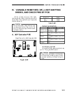
Page 104: ...al instruments and high accuracy A ADF Controller PCB Check Pins on the ADF Controller PCB Figure 5 401 Table 5 401 Normal Operating Mode Test Mode by DIP SW For a guide to LED indication in test mode see V C Using the DIP Switch Caution Some LEDs emit light even when they are off because of leakage current This is a normal condition and must be kept in mind Check pin Checks CP1 GND CP17 GND State...

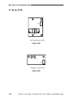
Page 105: ...OOTING 5 16 COPYRIGHT 1999 CANON INC CANON DADF B1 REV 0 APR 1999 PRINTED IN JAPAN IMPRIME AU JAPON B Sensor PCBs Last Original Sensor PCB Figure 5 402 Original Set Sensor PCB Figure 5 403 Q401 LED401 J401 J301 Q301 LED301 ...

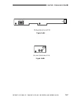
Page 106: ...ANON INC CANON DADF B1 REV 0 APR 1999 PRINTED IN JAPAN IMPRIME AU JAPON 5 17 CHAPTER 5 TROUBLESHOOTING Pre Registration Sensor PCB Figure 5 404 Reversal Outlet Sensor PCB Figure 5 405 Q201 LED201 J201 Q501 LED501 J501 ...

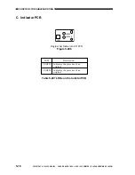
Page 107: ... REV 0 APR 1999 PRINTED IN JAPAN IMPRIME AU JAPON C Indicator PCB Original Set Indicator LED PCB Figure 5 406 Table 5 401 LEDs on the Indictor PCB LED Description LED301 Indicates the presence of an original LED302 Indicates the presence of an original LED301 LED302 J301 ...

Page 108: ...g the DIP Switch When the ADF is installed the copier s following service mode item will be disabled COPIER OPTION BODY FACE DWN Item Service mode DIP SW Sensor level adjustment FEEDER Function SENS INIT Original tray width adjustment 1st page registration position FEEDER Adjust DOCST adjustment Duplexing 2nd side registration FEEDER Adjust DOCST RP position adjustment Pickup delivery step operati...

Page 109: ...ce Manual 1 Starting Service Mode 1 Press the User Mode key on the copier s control panel 2 Press 2 and 8 on the key pad at the same time 3 Press the User Mode key once again The following screen will appear To use an ADF related item select FEEDER on the screen Figure 5 501 COPIER FEEDER SORTER FAX BOARD Initial items However FEEDER SORTER FAX and BOARD are displayed only if they are installed ...

Page 110: ...nal detected by the feeder ADJUST DOCST adjusts the original stop position for top pickup DOCST RP adjusts the original stop position for bottom pickup FUNCTION SENS INIT executes sensor auto sensitivity adjustment initialization for the ADF DBLT CLN executes separation roller cleaning mode for ADF OPTION SIZE SW turns on off the mix size detecting mechanism AB inch configuration originals SCAN SE...

Page 111: ...he left of the V marking increase the setting If the original is to the right of the V marking decrease the setting 5 Close the feeder and press OK so that the original will be discharged Be sure to discharge the original only in this way If you remove it manually the display will indicate the Jam message Note Standard stop position L4 11 0 1 mm L4 being the distance of the edge of the original fr...

Page 112: ...ast original sensor Be sure that the paper will not move and it will not cover the original sensor 2 Select the item and press OK In about 15 sec the original detection LED flashes twice While automatic adjustment is under way SERVICE will appear in the upper right corner of the service mode screen This item will end automatically in several seconds when the indication SERVICE changes to READY on ...

Page 113: ...he mechanism used to detect mixing of papers of different sizes AB inch 0 OFF disable 1 ON enable Use it to enable or disable the mechanism used to detect mixing of papers of different sizes non default 0 OFF non default size not detected 1 ON non default size detected Level 3 Description Remarks SIZE SW SCAN SEL Factory default 0 Factory default 0 FEEDER ...

Page 114: ...002 bit0 bit1 bit2 bit3 bit4 bit5 IPC read signal bit6 IPC write signal bit7 P003 bit0 Reversal outlet sensor TURN J7A 7 If 0 paper present light receiving U505 bit1 Pre registration sensor ENT J7B 3 if 0 paper present light receiving U502 bit2 Original Set sensor EMP J6A 13 If 0 paper present light receiving U503 bit3 Last original sensor LAST J6A 14 If 1 paper present light receiving U504 bit4 b...

Page 115: ...ensor SR8 ECVR J7B 9 When the delivery cover is opened 0 bit4 Pickup cover sensor SR2 SCVR J6A 6 When the pickup cover is opened 0 bit5 DF open closed sensor OPEN J7B 3 When the ADF is opened 0 bit6 bit7 P009 bit0 D A EMPLED0 bit1 D A EMPLED1 bit2 D A EMPLED2 bit3 D A EMPLED3 bit4 D A EMPLED4 bit5 D A EMPLED5 bit6 D A EMPLED6 bit7 D A EMPLED7 P010 bit0 DIP switch No 1 bit1 DIP switch No 2 bit2 DIP...

Page 116: ... to the counter reading at time of scheduled maintenance FEED indicates the number of pickup operations To check the number of scans made select COPIER COUNTER SCANNER SC TTL L FEED indicates the number of pickup operations for large size paper S FEED indicates the number of pickup operations for small size paper Figure 5 503 1 1 FEEDER READY FEED XXXXXXXX L FEED XXXXXXXX S FEED XXXXXXXX Display A...

Page 117: ...f the sensor by referring to LED1 and LED2 on the DF controller PCB The number of times LED1 flashes at 300 msec intervals indicates the sensor number It flashes at intervals of 300 msec remains off for 2 sec and repeats the sequence The following shows how each sensor may be identified 1 reversal outlet sensor 2 pre registration sensor 3 original sensor 4 last original sensor If LED2 remains on t...

Page 118: ...riginal If it is to the left in relation to the image leading edge shift bit 5 of the DIP switch DSW1 to ON if it is to the right shift bit 6 to ON Press the push switch SW1 as many times as necessary A single press causes a shift of 0 34 mm The original will be discharged automatically when the ADF is closed After adjustment shift all bits to OFF Shift bits 1 3 and 4 of the DIP switch DSW1 to ON ...

Page 119: ... OFF Use this item to execute cleaning of the separation roller Shift bit 3 of the DIP switch DSW1 to ON and press the push switch SW1 then close the ADF Place a sheet of copy paper on the original tray while holding onto its trailing edge so that the separation roller starts to rotate Hold on to the paper so that the separation roller will rotate idly on the paper Remove the copy paper when the s...

Page 120: ...F and turn off the power Use this item as a remedy in the event that the last original sensor U504 fails Shift bits 7 of the DIP switch to ON so as to disable the last original sensor After you have checked the operation be sure to shift all bits to OFF As a rule the last original sensor turns on in response to a press on the Copy Start key Use this mode to find out if the activation emission of l...

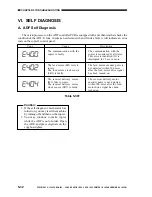
Page 121: ...ry motor M3 fails to rotate The reversal delivery motor clock sensor SR7 is faulty Caution 1 If the self diagnostic mechanism has turned on you may reset the machine by turning off and then on the copier 2 You may continue to make copies while the ADF is out of order Open the ADF and place originals on the copyboard glass Table 5 501 Code Cause Description The communication with the copier is moni...

Page 122: ...IMING CHART A 1 B SIGNALS AND ABBREVIATIONS A 5 C GENERAL CIRCUIT DIAGRAM A 7 D ADF CONTROLLER PCB A 8 E PRE REGISTRATION SENSOR PCB A 12 F REVERSAL OUTLET SENSOR PCB A 13 G ORIGINAL SET INDICATOR LED PCB A 15 H ORIGINAL SET SENSOR A 17 I LAST ORIGINAL SENSOR A 18 J SPECIAL TOOLS A 19 K SOLVENTS AND OILS A 20 ...

Page 123: ...sal delivery motor M3 Reversal delivery outlet sensor U505 Reversal delivery registration sensor SR5 Feed motor M2 Separate motor M1 Delivery sensor SR4 Reversal delivery inlet paper sensor SR4 Pre registration sensor U502 Original leading edge detected Original leading edge detected Original trailing edge detected Original trailing edge detected Delivery original leading edge detected 1st origina...

Page 124: ...ickup tray sensor EMP Brake BK1 Reversal delivery motor M3 Reversal delivery outlet sensor U505 Reversal delivery registration sensor SR5 Feed motor M2 Separate motor M1 Delivery sensor SR4 Reversal delivery inlet paper sensor SR4 Pre registration sensor U502 Original trailing edge detected Original leading edge detected Reversal original leading edge detected Original trailing edge detected Deliv...

Page 125: ...up tray sensor EMP Brake BK1 Reversal delivery motor M3 Reversal delivery outlet sensor U505 Reversal delivery registration sensor SR5 Feed motor M2 Separate motor M1 Delivery sensor SR4 Reversal delivery inlet paper sensor SR4 Pre registration sensor U502 Original leading edge detected Original trailing edge detected Original leading edge detected Original trailing edge detected 1st original sepa...

Page 126: ...Drive signal EJM Reversal Delivery Motor Rotation Speed Control signal EMPWM Reversal Delivery Motor Rotation Direction signal CW EMFWD Reversal Delivery Motor Rotation Direction signal CCW EMREV Reversal Delivery Motor Clock signal EMCK Pickup Unit Cover Open Closed Detection signal SCVR Pickup Detection signal SPR Original Set Indicator ON signal OGLED Original Pickup Tray Detection signal EMP L...

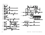
Page 127: ...1 2 2 1 3 2 1 2 3 1 2 1 TLN119B 2 3 1 2 1 2 1 3 2 1 2 1 3 2 1 1 2 3 1 2 3 1 2 3 1 2 3 3 2 1 1 2 3 1 2 3 J101 J102 J103 J301 J701 J201 J301 J701 J801 J401 MT3 MT2 J6A J6B J10 J3 J2 J9 1 2 3 2 1 1 2 3 1 2 3 3 2 1 3 2 1 1 2 MT1 GND RX1 TX1 GND 24U GND J100A J100A J100A J100A J100A J100A J100A 7 6 5 4 3 2 1 24V GND J100C J100C J100C J100 J100 3 2 1 EJM1 EJM2 J1 J5 J7 J401 J104 J104 SPM1 SPM2 FDM1 FDM2...

Page 128: ...8 3 2 1 2 1 2 2 2 NC1 NC2 OUT NC3 GND1 NC4 FB NC5 VIN NC7 GND5 GND4 GND3 GND2 NC6 ON 1 2 3 4 5 6 7 8 16 15 14 13 12 11 10 9 1 1 2 3 1 2 1 2 2 1 1 1 D2 FU1 1 9 2 6 HC14 Q6 R35 C15 C16 L1 CP17 GND ETH2 R36 Q19 R20 R19 Q17 R18 R38 R17 D3 C17 R21 RXD1 TXD1 HC14 5 2 1 2 C13 1 2 1 2 C14 ETH1 CB1 1 2 3 4 5 6 7 8 J3 J3 J3 J3 J3 J3 J3 J3 J1 J1 J1 J1 J1 J1 J1 GND RX1 TX1 GND 24U GND J2 J2 GND RX2 GND 5V GND...

Page 129: ... Q20 3 2 1 24V 5V 5V 5V R34 R86 C34 C35 Q16 Q15 Q10 D12 R84 R85 R87 C33 24V 24V 24U 5V 3 2 1 Q22 3 3 3 2 1 Q24 Q25 Q27 3 2 1 2 1 Q26 D8 C18 2 1 C19 C20 C41 R22 R24 24V 2 1 C23 2 1 C22 R32 R33 R31 R30 R120 R121 R23 R25 R118 R119 R27 R6 R92 R109 R110 R108 Q13 R26 R29 2 1 Q21 2 1 Q23 3 2 1 Q31 3 Q30 2 1 3 1 2 Q29 J9 J9 EJM1 EJM2 1 2 3 Q28 1 2 J5 J5 J5 J5 J5 J5 1 2 3 4 5 6 2 1 3 3 1 2 1 2 R88 R90 R91 ...

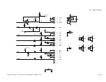
Page 130: ...16 R58 R94 Q39 Q38 Q37 Q10 Q41 R60 R61 CP5 LASTS CP4 EMPS C36 Q6 J6 R114 D15 5V 5V 5V 5V D14 R93 5V D10 R51 R50 R46 FCLK CP11 CP1 CP14 FCLK WIDTH ENTLED ENTS GND C24 5V R41 5V R47 24U 1 1 2 WIDTH C26 CP6 ENTLED ENTS ORGLED C43 1 1 1 CP2 1 1 2 C25 C44 1 2 1 2 1 2 1 2 2 3 1 4 8 1 2 24U 6 5 2R 2R 2R 2R 2R 2R 2R 2R 2R 1R 1R 1R 1R 1R 1R 1R EMPLED7 EMPLED6 EMPLED5 EMPLED4 EMPLED3 EMPLED2 EMPLED1 EMPLED0...

Page 131: ... J7 J7 J7 J7 J7 J7 J7 J7 J7 J7 J7 GND 5V 24U TNLED TURN 5V GND EREG 5V GND EENT 5V GND ECVR GND EMCK 5V 5V GND OPEN A7 A4 A5 A6 A1 A2 A3 B7 B8 B9 B4 B5 B6 B1 B2 B3 B10 B11 R117 TURNLED TURNS TURNS EENTS EREGIS ECVRS ECLK ECLK CP7 TURNLED OPENS Q42 Q40 R77 1 1 2 2 1 1 1 2 1 2 C45 1 2 1 7 14 2 1 2 6 5 7 Q8 Q9 C37 Q6 9 13 12 HC14 HC08 HC08 VCC GND 5V 1 7 14 2 Q7 C39 HC14 VCC GND 5V 1 7 14 2 Q8 C38 HC...

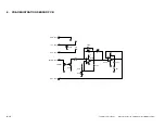
Page 132: ...PRINTED IN JAPAN IMPRIME AU JAPON E PRE REGISTRATION SENSOR PCB 2 1 4 5 3 J201 J201 J201 C201 C202 C203 JP1 R201 R203 R204 R205 D201 JP2 Q201 Q202 5V 5V 24U 24U J201 J201 GND 5V 24U ETLED ENT LED201 2 1 2 1 2 2 2 1 3 1 1 3 2 1 2 1 4 8 Q202 24U 6 5 7 4 2 2 1 1 8 ...

Page 133: ...99 PRINTED IN JAPAN IMPRIME AU JAPON A 13 F REVERSAL OUTLET SENSOR PCB 2 1 4 5 3 J501 J501 J501 C501 C502 C503 R501 R503 R504 R505 D501 Q501 Q502 5V 5V 24U 24U J501 J501 GND 5V 24U TNLED TURN LED501 2 1 1 2 2 1 3 2 1 3 2 1 2 1 4 8 Q502 24U 6 5 7 4 2 1 8 ...

Page 134: ...COPYRIGHT 1999 CANON INC CANON DADF B1 REV 0 APR 1999 PRINTED IN JAPAN IMPRIME AU JAPON A 15 APPENDIX G ORIGINAL SET INDICATOR LED PCB LED301 R301 J301 2 2 J301 5V OGLED 1 1 LED302 R302 2 1 ...

Page 135: ...JAPON A 17 H ORIGINAL SET SENSOR J301 J301 J301 C301 C302 C304 C307 Q302 D302 R301 R302 R303 R304 R305 R306 D301 C305 R307 R308 C303 Q301 Q302 5V 5V 24U 24U J301 J301 GND 5V 24U EPLED EMP LED301 2 1 2 2 1 C306 R309 2 1 3 1 1 2 1 2 1 2 1 2 3 1 2 2 1 4 8 2 1 24U 6 5 7 4 8 2 1 4 5 1 2 3 ...

Page 136: ...IGINAL SENSOR J401 J401 J401 C401 C402 C404 C407 Q402 R401 R402 R403 R404 R405 R406 D401 R407 R412 C405 R408 C403 Q401 Q402 5V 5V 24U 24U J401 J401 GND 5V 24U LTLED LAST LED401 2 1 2 2 1 C406 R409 R411 R410 D402 2 1 3 1 1 2 1 2 3 1 2 2 1 4 8 2 1 2 1 24U 6 1 2 5 7 4 8 2 1 4 5 1 2 3 C409 R413 2 1 2 1 C408 ...

Page 137: ... Tool No FY9 2002 000 FY9 3038 000 FY9 3039 000 Shape Rank A A A Shape For making electrical checks Use it in combination with the laser power checker when adjusting the intensity of the laser For adapting the meter probe when making electrical checks For adapting the meter probe when making electrical checks Reference The ranking notations indicate the following A Each service person is expected ...

Page 138: ...o 1 2 Name Ethyl alcohol Ethanol Isopropyl alcohol Isopropa nol Lubricant Uses Cleaning e g glass plastic rubber parts external covers Lubricating e g drive and friction parts Composition C2 H5 O CHZ3 2 CHOH Silicone oil Remarks Do not bring near fire Procure locally Isopropyl alcohol may be substituted Toll No CK 0551 20 g ...

Page 139: ...Prepared by OfficeImagingProductsTechnicalSupportDivision OfficeImagingProductsQualityAssuranceCenter CANONINC PrintedinJapan REVISION0 APR 30809 5 7 Hakusan7 chome Toride Ibaraki 302 8501Japan ...

Page 140: ...0996S9 9 1 PRINTED IN JAPAN IMPRIME AU JAPON This publication is printed on 70 reprocessed paper ...

Reviews: