COPYRIGHT © 1999 CANON INC.
CANON DADF-B1 REV.0 APR. 1999 PRINTED IN JAPAN (IMPRIME AU JAPON)
2-13
CHAPTER 2 BASIC OPERATION
2. Moving Up the Pickup Roller Unit
The pickup roller and the lifter are designed to operate (move up and down) in conjunction with
the separation motor (M1).
n
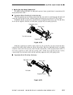
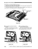
Separation Motor Rotating Counterclockwise
When the separation motor rotates counterclockwise, the work of a cam disengages the lock used
to keep the pickup roller in place, and the pickup roller starts to move down on its own weight.
In addition, the drive reaches the arm of the lifter, causing the lifter to move up. This operation
moves up the originals while they are held intact in preparation for pickup operation.
Figure 2-212
Figure 2-213
Separation motor
Pickup roller
Lifter
Separation roller
Counter clockwise
When the separation motor (M1) rotates clockwise, the work of the cam moves down the lifter,
and then the pickup roller returns to the ascent position. When the separation motor is rotating
clockwise, the work of the one-way clutch lets the rotation drive of the separation motor (M1) to
reach the separation roller and the pickup roller. When the separation motor rotates
counterclockwise, its rotation drive will not reach the separation roller or the pickup roller.
n
Separation Motor Rotating Clockwise
Separation motor
Pickup roller
Separation roller
Lifter
Clockwise


