CHAPTER 3 MECHANICAL SYSTEM
3-14
COPYRIGHT © 1999 CANON INC.
CANON DADF-B1 REV.0 APR. 1999 PRINTED IN JAPAN (IMPRIME AU JAPON)
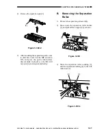
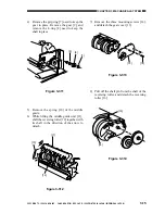
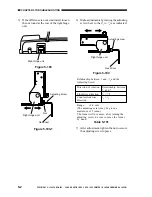
8) Move the stopper up and down slightly to
make sure that the stopper is in the groove
of the separation roller coupling.
Figure 3-309-1
E.
Removing the Reversing
Roller and Feed Roller
1) Remove the reversal delivery unit. (See E.
“Removing the Reversal Delivery Unit”
under II. “Drive System.”)
2) Remove the reversal delivery motor. (See
E. “Removing the Reversal Delivery
Motor” under II. “Drive System.”)
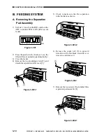
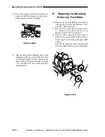
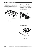
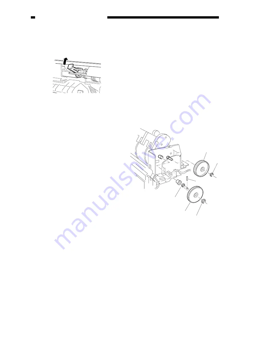
3) Remove the E-rings [1] and [2] used to
keep the two gears in place; then, remove
the E-ring [3] used to keep the main shaft
in place.
Pull off the shaft pin [4] from the main
shaft, and detach the two gears [5] and [6].
Figure 3-310
[3]
[2]
[6]
[5]
[1]
[4]
9) After mounting the separation pad or the
separation roller, be sure to shift bits 3 and
6 of the DIP switch to ON, and press the
push switch (lifter descent mode; in about
3 sec, the lifter will move down and stop
automatically).


