CHAPTER 5 TOROUBLESHOOTING
5-10
COPYRIGHT © 1999 CANON INC.
CANON DADF-B1 REV.0 APR. 1999 PRINTED IN JAPAN (IMPRIME AU JAPON)
A. Troubleshooting Malfunctions
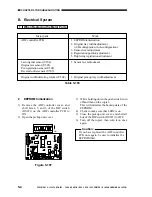
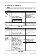
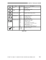
Table 5-202
Caution:
If no operation occurs in response to the push switch, be sure to turn off the main power as soon
as possible when using the DIP switch on the ADF controller PCB to make a check.
2.
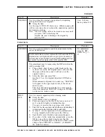
E402
Cause
Feed motor
clock sensor
(SR1)
Drive
mechanism
(gear, belt;
damage)
Feed motor
(M2)
Step
1
2
3
Checks
Set the meter to the DC (V) range,
and connect its + probe to the
connector J6A0-2 and its - robe to
the connector J6A-1. Does the
voltage alternate between 5 and 0
V when the feed belt is moved
slightly by hand?
Does the gear, motor, and belt
operate smoothly when the feed
belt is moved clockwise/
counterclockwise?
Set the meter to the DC (V) range,
and connect its + probe to J5-4
and its - probe to J5-3 on the ADF
controller PCB. Shift bits 2, 5, 6,
and 7 of the DIP switch, and press
the push switch. Is the reading of
the meter about 24 V when the
ADF open/closed detecting lever
is pushed?
· To stop the ongoing operation,
Press the push switch.
At the end of the operation, be
sure to shift all bits of the DIP
switch to OFF.
Yes/No
NO
NO
YES
NO
Action
Check the wiring from the
feed motor clock sensor to the
AD controller PCB; if normal,
replace the feed motor clock
sensor.
Check the gear and the belt.
Check the wiring from the
feed motor to the ADF
controller PCB; if normal,
replace the feed motor.
Replace the ADF controller
PCB.
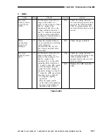
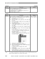
Table 5-201
Cause
Wiring
ADF
controller
PCB
Step
1
2
3
Checks
Turn off and then on the power
switch. Is the problem corrected?
Set the meter to the DC (V)
range, and connect its probes to
the following terminals. Is the
voltage about 24 V for each?
Replace the ADF controller PCB.
Is the problem corrected?
Yes/No
YES
NO
YES
NO
Action
End. (Check the wiring
between the copier's image
processor PCB and the ADF
controller PCB.)
Check the wiring for the
power supplied by the copier.
End.
Replace the copier's image
processor PCB.
1.
E400/E712
+ probe
- probe
1
J2-1
J2-2
2
J1-6
J1-7

