Chapter 2
2-3
F-2-2
2.1.6
Height
0003-1849
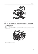
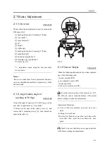
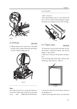
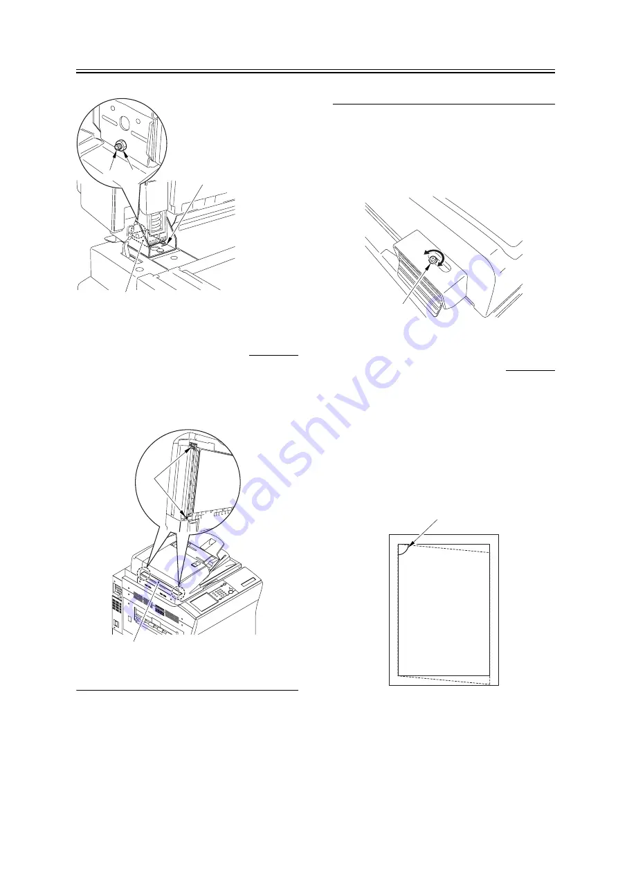
1) With the machine closed, check to see if the height
adjusting rolls [1] found at the left rear and front are
in contact with the reading glass [2].
F-2-3
Memo:
To facilitate the work, try executing the following to
turn on the scanning lamp using the host machine's
service mode: COPIER>FUNCTION>MISC-
R>SCANLAMP.
<If Not in Contact>
If the height adjusting rolls [1] at the left front and
rear are not in contact with the reading glass [2],turn
the fixing screw [3] found at the top of the left hinge.
F-2-4
2.1.7
Right Angle
0003-2252
The following steps adjust the relationship between
the machine's original feed direction and the host
machine's scanner system:
1) Place the Test Chart in the machine, and make a
copy.
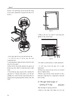
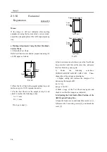
2) Check the right angle of the image in relation to the
leading edge of the output (i.e., angle A).
F-2-5
3) Loosen the 2 knurled screws found at the front of
the right hinge unit.
4) Bend over the edge of the rubber cover [2] found at
[1]
[2]
[3]
[4]
[1]
[2]
[3]
[A]
Summary of Contents for DADF-M1
Page 1: ...Feb 21 2005 Portable Manual Feeder DADF M1 ...
Page 2: ......
Page 6: ......
Page 9: ...Chapter 1 Maintenance and Inspection ...
Page 10: ......
Page 12: ......
Page 26: ...Chapter 1 1 14 F 1 20 F 1 21 4 Clean the top face plastic film 1 of the prism 1 2 1 ...
Page 31: ...Chapter 2 Standards and Adjustments ...
Page 32: ......
Page 34: ......
Page 44: ......
Page 45: ...Chapter 3 Error Code ...
Page 46: ......
Page 47: ...Contents Contents 3 1 User Error Code 3 1 3 1 1 Alarm Code 3 1 ...
Page 48: ......
Page 50: ......
Page 51: ...Chapter 4 Outline of Components ...
Page 52: ......
Page 54: ......
Page 59: ...Chapter 5 System Construction ...
Page 60: ......
Page 62: ......
Page 69: ...Feb 21 2005 ...
Page 70: ......


