Chapter 2
2-5
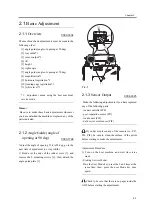
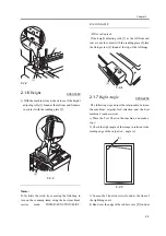
mount the angle guide plate [3] in place using 2
screws [2].
F-2-9
2.1.9
Magnification
0003-2302
Memo:
To adjust the magnification, compare an image made
in stream reading mode and an image made in
copyboard mode. Unlike other ADFs, you will not be
comparing a copy image and its original
.
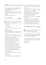
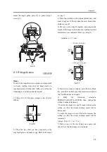
1) Using A4 or LTR paper, prepare a test chart as
follows:
F-2-10
2) Place the test chart you have prepared on the
copyboard glass, and make a copy. Refer to the output
as copy A.
3) Place the test chart in the original pickup tray, and
make a copy at a 100% reproduction ratio. Refer to the
output as copy B.
4) Put copy A and copy B together, and compare the
length of the image in feed direction, making sure that
dimension a is as indicated. If not, go to step 5).
standard: a </= 1 mm
F-2-11
5) Start service mode as follows: press the User Mode
key, press the 2 and 8 keys at the same time, and press
the User Mode key once again.
6) Make the following selections:
FEEDER>ADJUST>LA-SPEED; then, change the
setting to make adjustments.
-To make the image on copy B longer, decrease the
setting (so that the stream reading speed will be
decreased).
To make the image on copy B shorter, increase the
setting (so that the stream reading speed will be
increased).
[ range -30 to 30 : -3 to + 3 % ]
7) Make a copy of the text charge once again, and
check to see that the image is as indicated.
[2]
[1]
[3]
[1]
Right angle
10mm
10mm
10mm
10mm
Feed
direction
Copy A
Copy B
a
Feed
direction
Copy A
Copy B
a
<If Cop A Is Shorter>
<If Copy A Is Longer>
Summary of Contents for DADF-M1
Page 1: ...Feb 21 2005 Portable Manual Feeder DADF M1 ...
Page 2: ......
Page 6: ......
Page 9: ...Chapter 1 Maintenance and Inspection ...
Page 10: ......
Page 12: ......
Page 26: ...Chapter 1 1 14 F 1 20 F 1 21 4 Clean the top face plastic film 1 of the prism 1 2 1 ...
Page 31: ...Chapter 2 Standards and Adjustments ...
Page 32: ......
Page 34: ......
Page 44: ......
Page 45: ...Chapter 3 Error Code ...
Page 46: ......
Page 47: ...Contents Contents 3 1 User Error Code 3 1 3 1 1 Alarm Code 3 1 ...
Page 48: ......
Page 50: ......
Page 51: ...Chapter 4 Outline of Components ...
Page 52: ......
Page 54: ......
Page 59: ...Chapter 5 System Construction ...
Page 60: ......
Page 62: ......
Page 69: ...Feb 21 2005 ...
Page 70: ......

