Chapter 5
5-1
5.1
Basic Construction
5.1.1
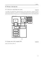
Overview of the Electrical Circuitry
0002-7181
The machine is not equipped with a controller PCB, and its electrical mechanisms are controlled by the reader
controller PCB, which serves as a CPU (IC1). The CPU interprets signals from sensors and the host machine to
generate signals used to drive DC loads (e.g., motor, solenoid) with the help of the CPU (IC9) of the ADF driver PCB.
F-5-1
5.1.2
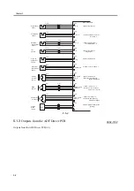
Inputs to the ADF Controller PCB
0002-7187
Inputs to the ADF Driver PCB (1/1)
ADF driver PCB
CPU
(IC9)
5 VDC
power supply
(IC10)
CPU
(IC1)
FLASH ROM
(IC3)
EEP ROM
(IC4,IC5)
IRC
(IC2)
Reader controller PCB
Power supply PCB
Sensor
Original
indication
LED PCB
Motor
Solenoid
Clutch
+13V
+24
+5
Host machine
Serial
communication
Summary of Contents for DADF-M1
Page 1: ...Feb 21 2005 Portable Manual Feeder DADF M1 ...
Page 2: ......
Page 6: ......
Page 9: ...Chapter 1 Maintenance and Inspection ...
Page 10: ......
Page 12: ......
Page 26: ...Chapter 1 1 14 F 1 20 F 1 21 4 Clean the top face plastic film 1 of the prism 1 2 1 ...
Page 31: ...Chapter 2 Standards and Adjustments ...
Page 32: ......
Page 34: ......
Page 44: ......
Page 45: ...Chapter 3 Error Code ...
Page 46: ......
Page 47: ...Contents Contents 3 1 User Error Code 3 1 3 1 1 Alarm Code 3 1 ...
Page 48: ......
Page 50: ......
Page 51: ...Chapter 4 Outline of Components ...
Page 52: ......
Page 54: ......
Page 59: ...Chapter 5 System Construction ...
Page 60: ......
Page 62: ......
Page 69: ...Feb 21 2005 ...
Page 70: ......


