Chapter 2
2-7
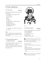
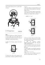
F-2-14
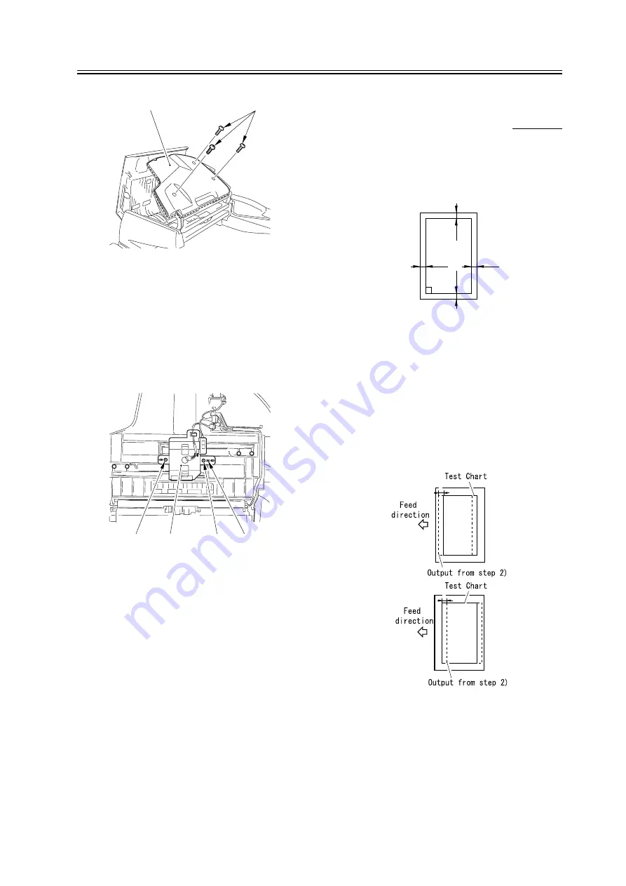
3) Loosen the mounting screw [1], and remove the
screw [2] from the positioning hole, and fit it and
temporarily tighten it in the adjusting angular hole [3].
- if A > 1 mm, move the volume unit [6] to the
front.
- if B > 1 mm, move the volume unit [6] to the rear.
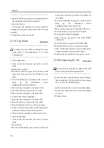
F-2-15
4) Move the original width volume unit [4] to the front
or the rear to make adjustments.
5) Tighten the screw [1] that has been tentatively
tightened and the screw [3] that has been fitted in the
adjusting angular hole.
6) When done, mount back the cover.
7) Make a copy of the Test Chart once again, and see
that the image is as indicated.
2.1.11
Leading Edge
Registration
0003-2362
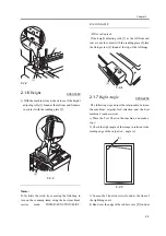
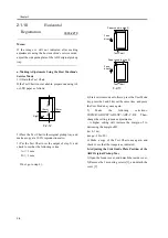
1) Obtain the Text Chart.
If the Text Chart is not available, make one using A4
or LTR paper as follows:
F-2-16
2) Place the Text Chart in the original tray, and make
a copy of it at a 100% reproduction ratio.
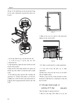
3) Check to see that dimension A of the Test Chart and
the image obtained in step 2) are as indicated:
A </= 1 mm
B </= 1 mm
If not, go to step 4).
F-2-17
4) Start service mode as follows: press the User Mode
key, press the 2 and 8 keys at the same time, and press
the User Mode key once again.
[1]
[2]
[1]
[2]
[3]
[4]
Right angle
10mm
10mm
10mm
10mm
A
B
Summary of Contents for DADF-M1
Page 1: ...Feb 21 2005 Portable Manual Feeder DADF M1 ...
Page 2: ......
Page 6: ......
Page 9: ...Chapter 1 Maintenance and Inspection ...
Page 10: ......
Page 12: ......
Page 26: ...Chapter 1 1 14 F 1 20 F 1 21 4 Clean the top face plastic film 1 of the prism 1 2 1 ...
Page 31: ...Chapter 2 Standards and Adjustments ...
Page 32: ......
Page 34: ......
Page 44: ......
Page 45: ...Chapter 3 Error Code ...
Page 46: ......
Page 47: ...Contents Contents 3 1 User Error Code 3 1 3 1 1 Alarm Code 3 1 ...
Page 48: ......
Page 50: ......
Page 51: ...Chapter 4 Outline of Components ...
Page 52: ......
Page 54: ......
Page 59: ...Chapter 5 System Construction ...
Page 60: ......
Page 62: ......
Page 69: ...Feb 21 2005 ...
Page 70: ......

